Toyota Corolla Cross: Installation
INSTALLATION
CAUTION / NOTICE / HINT
COMPONENTS (INSTALLATION)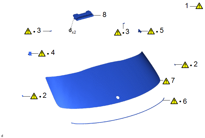
|
Procedure | Part Name Code |
.png) |
.png) |
 |
|---|---|---|---|---|---|
|
1 | CLEAN BACK DOOR GLASS SUB-ASSEMBLY |
68131 |
|
- | - |
|
2 | BACK DOOR WINDOW FRAME SPACER |
68699 |
|
- | - |
|
3 | NO. 2 BACK DOOR GLASS ADHESIVE DAM |
68294D |
|
- | - |
|
4 | NO. 2 BACK WINDOW GLASS SPACER |
64819B |
|
- | - |
|
5 | NO. 1 BACK WINDOW GLASS SPACER |
64818B |
|
- | - |
|
6 | BACK DOOR WINDOW GLASS ADHESIVE DAM |
64813B |
|
- | - |
|
7 | BACK DOOR GLASS SUB-ASSEMBLY |
- |
|
- | - |
|
8 | CENTER STOP LIGHT ASSEMBLY |
81570 | - |
- | - |
|
● | Non-reusable part |
- | - |
|
Procedure | Part Name Code |
|
|
| |
|---|---|---|---|---|---|
|
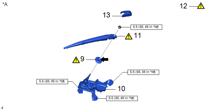
9 | REAR WIPER MOTOR GROMMET |
85143R |
|
- | - |
|
10 | REAR WIPER MOTOR ASSEMBLY |
85110R | - |
- | - |
|
11 | INSTALL REAR WIPER ARM AND BLADE ASSEMBLY |
- |
|
- | - |
|
12 | INSPECT REAR WIPER ARM AND BLADE ASSEMBLY |
- |
|
- | - |
|
13 | REAR WIPER ARM HEAD CAP |
85292A | - |
- | - |
|
*A | w/ Rear Wiper |
- | - |
.png) |
N*m (kgf*cm, ft.*lbf): Specified torque |
.png) |
MP grease |
|
Procedure | Part Name Code |
|
|
| |
|---|---|---|---|---|---|
|
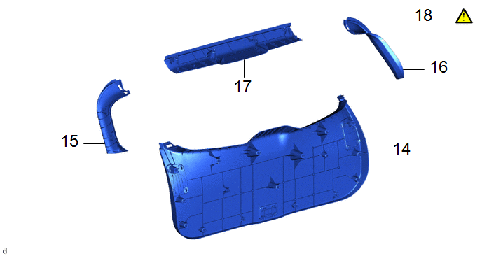
14 | BACK DOOR TRIM PANEL ASSEMBLY |
64780A | - |
- | - |
|
15 | BACK DOOR SIDE GARNISH LH |
67938A | - |
- | - |
|
16 | BACK DOOR SIDE GARNISH RH |
67937B | - |
- | - |
|
17 | UPPER BACK DOOR TRIM PANEL ASSEMBLY |
64790B | - |
- | - |
|
18 | INSPECT FOR LEAK |
- |
|
- | - |
CAUTION / NOTICE / HINT
NOTICE:
Make sure to use Toyota Genuine Windshield Glass Adhesive (High Modulus Type) or equivalent.
PROCEDURE
1. CLEAN BACK DOOR GLASS SUB-ASSEMBLY

(1) When reusing the back door glass sub-assembly.
1. Using a scraper, remove any remaining adhesive residue from the back door glass sub-assembly.
NOTICE:
Be careful not to damage the back door glass sub-assembly.
(2) Clean the outer circumference of the back door glass sub-assembly with a non-residue solvent.
NOTICE:
- Do not touch the back door glass sub-assembly surface after cleaning it.
- Even if using a new back door glass sub-assembly, clean it with a non-residue solvent.
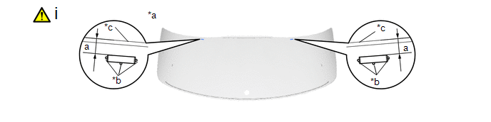
2. INSTALL BACK DOOR WINDOW FRAME SPACER

|
*a | Back Side of Back Door Glass Sub-assembly |
*b | Ag Print Mark |
|
*c | Back Door Glass Sub-assembly Edge Side |
- | - |
(1) Install the back door window frame spacer by the below procedure.
1. Using a brush or sponge, coat the installation area of the back door window frame spacer with glass primer.
NOTICE:
- Do not apply too much glass primer.
- Allow the glass primer to dry for 3 minutes or more.
- Throw away any leftover glass primer.
HINT:
If an area other than specified is coated by accident, wipe off the glass primer with a clean piece of cloth before it dries.
2. Install 2 new back door window frame spacers to the back door glass sub-assembly as shown in the illustration.
Standard Dimension:
|
Area | Dimension |
Area | Dimension |
|---|---|---|---|
|
a | 20.5 to 24.5 mm (0.807 to 0.965 in.) |
- | - |
3. INSTALL NO. 2 BACK DOOR GLASS ADHESIVE DAM
|
*a | Back Side of Back Door Glass Sub-assembly |
*b | Ag Print Mark |
|
*c | Back Door Glass Sub-assembly Edge Side |
- | - |
(1) Install the No. 2 back door glass adhesive dam by the below procedure.
1. Using a brush or sponge, coat the installation area of the No. 2 back door glass adhesive dam with glass primer.
NOTICE:
- Do not apply too much glass primer.
- Allow the glass primer to dry for 3 minutes or more.
- Throw away any leftover glass primer.
HINT:
If an area other than specified is coated by accident, wipe off the glass primer with a clean piece of cloth before it dries.
2. Install 2 new No. 2 back door glass adhesive dams to the back door glass sub-assembly as shown in the illustration.
Standard Dimension:
|
Area | Dimension |
Area | Dimension |
|---|---|---|---|
|
a | 9.0 to 13 mm (0.354 to 0.512 in.) |
- | - |
4. INSTALL NO. 2 BACK WINDOW GLASS SPACER

|
*a | Back Side of Back Door Glass Sub-assembly |
*b | Ag Print Mark |
(1) Install the No. 2 back window glass spacer by the below procedure.
1. Using a brush or sponge, coat the installation area of the No. 2 back window glass spacer with glass primer.
NOTICE:
- Do not apply too much glass primer.
- Allow the glass primer to dry for 3 minutes or more.
- Throw away any leftover glass primer.
HINT:
If an area other than specified is coated by accident, wipe off the glass primer with a clean piece of cloth before it dries.
2. Install a new No. 2 back window glass spacer to the back door glass sub-assembly as shown in the illustration.
5. INSTALL NO. 1 BACK DOOR GLASS SPACER
6. INSTALL BACK DOOR WINDOW GLASS ADHESIVE DAM

|
*a | Back Side of Back Door Glass Sub-assembly |
*b | Ceramic Notch |
(1) Install the back door window glass adhesive dam by the below procedure.
1. Using a brush or sponge, coat the installation area of the back door window glass adhesive dam with glass primer.
NOTICE:
- Do not apply too much glass primer.
- Allow the glass primer to dry for 3 minutes or more.
- Throw away any leftover glass primer.
HINT:
If an area other than specified is coated by accident, wipe off the glass primer with a clean piece of cloth before it dries.
2. Install a new back door window glass adhesive dam to the back door glass sub-assembly as shown in the illustration.
7. INSTALL BACK DOOR GLASS SUB-ASSEMBLY
.png) |
Adhesive | - |
- |
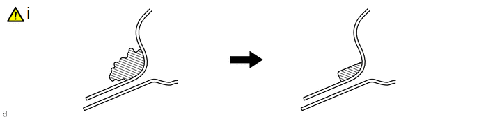
(1) Clean and shape the contact surface of the vehicle body.
1. Using a knife, cut away excess adhesive on the contact surface of the vehicle body as shown in the illustration.
NOTICE:
Leave as much adhesive on the vehicle body as possible.

|
*a | Matchmark |
*b | Suction Cup |
(1) Prepare to install the back door glass sub-assembly by the below procedure.
1. Using suction cups, place the back door glass sub-assembly in the correct position.
2. Check that the whole contact surface of the back door glass sub-assembly rim is perfectly even.
3. Align the matchmarks on the back door glass sub-assembly and vehicle body.
NOTICE:
Check that the back window glass spacers are engaged to the vehicle body correctly.
4. Remove the back door glass sub-assembly.
(2) Using a brush, coat the installation surface on the vehicle body with body primer.
NOTICE:
- Do not coat the adhesive with body primer.
- Do not apply too much body primer.
- Allow the body primer to dry for 3 minutes or more.
- Throw away any leftover body primer.
HINT:
If an area other than specified is coated by accident, wipe off the body primer with a clean piece of cloth before it dries.
|
*1 | No. 2 Back Door Glass Adhesive Dam |
*2 | Back Door Window Glass Adhesive Dam |
|
*a | Back Side of Back Door Glass Sub-assembly |
- | - |
|
|
Glass Primer | - |
- |
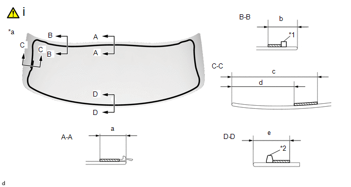
(1) Using a brush or sponge, coat the adhesive application area with glass primer as shown in the illustration.
Standard Dimension:
|
Area | Dimension |
Area | Dimension |
|---|---|---|---|
|
a | 26.3 mm (1.04 in.) or more |
b | 29.1 mm (1.15 in.) or more |
|
c | 80.4 mm (3.17 in.) or more |
d | 58.4 mm (2.30 in.) |
|
e | 28.6 mm (1.13 in.) or more |
- | - |
NOTICE:
- Do not apply too much glass primer.
- Allow the glass primer to dry for 3 minutes or more.
- Throw away any leftover glass primer.
HINT:
- Apply glass primer onto the ceramic notches.
- If an area other than specified is coated by accident, wipe off the glass primer with a clean piece of cloth before it dries.
|
*1 | No. 2 Back Door Glass Adhesive Dam |
*2 | Back Door Window Glass Adhesive Dam |
|
*a | Cartridge Nozzle |
*b | Back Side of Back Door Glass Sub-assembly |
|
|
Adhesive | - |
- |
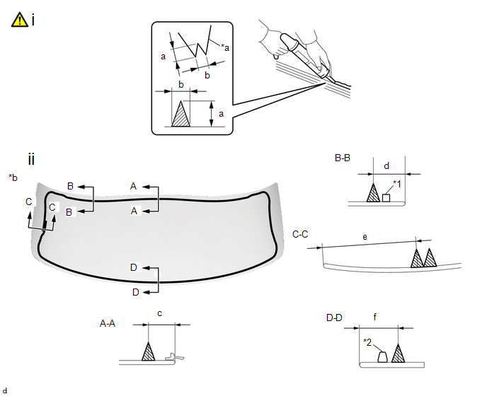
(1) Prepare to apply adhesive to the back door glass sub-assembly by the below procedure.
Adhesive:
Toyota Genuine Windshield Glass Adhesive (High modulus type) or equivalent
1. Cut off the tip of the cartridge nozzle as shown in the illustration.
Standard Dimension:
|
Area | Dimension |
Area | Dimension |
|---|---|---|---|
|
a | 12 to 15 mm (0.472 to 0.591 in.) |
b | 8.0 to 11 mm (0.315 to 0.433 in.) |
2. Load the sealer gun with the cartridge.
(2) Apply adhesive to the back door glass sub-assembly as shown in the illustration.
Standard Dimension:
|
Area | Dimension |
Area | Dimension |
|---|---|---|---|
|
c | 19.3 mm (0.760 in.) |
d | 22.1 mm (0.870 in.) |
|
e | 65.2 mm (2.57 in.) |
f | 21.6 mm (0.850 in.) |
|
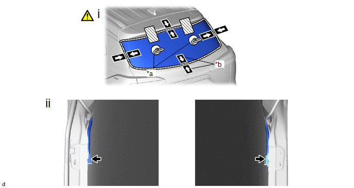
*a | Suction Cup |
*b | Matchmark |
(1) Install the back door glass sub-assembly by the below procedure.
1. Using suction cups, position the back door glass sub-assembly so that the matchmarks are aligned, and press it in gently along the rim.
NOTICE:
- Check that the back window glass spacers are engaged to the vehicle body correctly.
- Check the clearance between the vehicle body and back door glass sub-assembly.
2. Lightly press the outer surface of the back door glass sub-assembly to ensure that the back door glass sub-assembly is securely fit to the vehicle body.
HINT:
Press the glass with a force of 98 N (10 kgf, 22.0 lbf) or more.
3. Using a scraper, remove any excess or protruding adhesive.
4. Hold the back door glass sub-assembly using protective tape until the applied adhesive becomes hard.
HINT:
Follow the instructions supplied by the adhesive manufacturer or in the corresponding instruction manual for the minimum amount of time necessary to wait before driving the vehicle.
(2) Connect the 2 connectors.
8. INSTALL CENTER STOP LIGHT ASSEMBLY
9. INSTALL REAR WIPER MOTOR GROMMET (w/ Rear Wiper)
|
|
Click here |
10. INSTALL REAR WIPER MOTOR ASSEMBLY (w/ Rear Wiper)
Click here
.gif)
11. INSTALL REAR WIPER ARM AND BLADE ASSEMBLY (w/ Rear Wiper)
|
|
Click here |
12. INSPECT REAR WIPER ARM AND BLADE ASSEMBLY (w/ Rear Wiper)
Click here
13. INSTALL REAR WIPER ARM HEAD CAP (w/ Rear Wiper)
14. INSTALL BACK DOOR TRIM PANEL ASSEMBLY
15. INSTALL BACK DOOR SIDE GARNISH LH
16. INSTALL BACK DOOR SIDE GARNISH RH
17. INSTALL UPPER BACK DOOR TRIM PANEL ASSEMBLY
18. INSPECT FOR LEAK

(1) Inspect for leaks by the below procedure.
1. After the adhesive has hardened, apply water from the outside of the vehicle. Check that no water leaks into the cabin.
2. If water leaks into the cabin, allow the water to dry and add adhesive.
3. Remove the protective tape.


