Toyota Corolla Cross: Installation
INSTALLATION
CAUTION / NOTICE / HINT
COMPONENTS (INSTALLATION)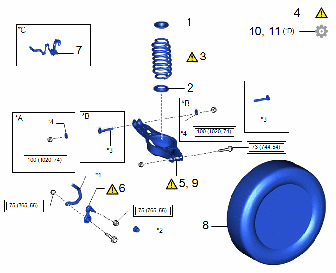
|
Procedure |
Part Name Code |
.png) |
.png) |
.png) |
|
|---|---|---|---|---|---|
|
1 |
REAR UPPER COIL SPRING INSULATOR |
48471C |
- |
- |
- |
|
2 |
REAR LOWER COIL SPRING INSULATOR |
48259A |
- |
- |
- |
|
3 |
REAR COIL SPRING |
48231B |
|
- |
- |
|
4 |
STABILIZE SUSPENSION |
- |
|
- |
- |
|
5 |
FULLY TIGHTEN REAR NO. 2 SUSPENSION ARM ASSEMBLY (for Rear Axle Carrier Sub-assembly Side) |
48740F |
|
- |
- |
|
6 |
REAR STABILIZER LINK ASSEMBLY |
48840A |
|
- |
- |
|
7 |
REAR HEIGHT CONTROL SENSOR SUB-ASSEMBLY LH (for LH Side) |
89408C |
- |
- |
- |
|
8 |
REAR WHEEL |
- |
- |
- |
- |
|
9 |
FULLY TIGHTEN REAR NO. 2 SUSPENSION ARM ASSEMBLY (for Rear Suspension Member Sub-assembly Side) |
48740F |
|
- |
- |
|
10 |
INSPECT AND ADJUST REAR WHEEL ALIGNMENT |
- |
- |
- |
|
|
11 |
PERFORM CALIBRATION |
- |
- |
- |
|
|
*A |
for Gasoline Model |
*B |
for HEV Model |
|
*C |
for LH Side |
*D |
w/ Parking Assist Monitor System |
|
*1 |
REAR STABILIZER BAR |
*2 |
CAP |
|
*3 |
REAR SUSPENSION TOE ADJUST CAM SUB-ASSEMBLY |
*4 |
NO. 2 CAMBER ADJUST CAM |
.png) |
Tightening torque for "Major areas involving basic vehicle performance such as moving/turning/stopping" : N*m (kgf*cm, ft.*lbf) |
- |
- |
CAUTION / NOTICE / HINT
HINT:
- Use the same procedure for the RH side and LH side.
- The following procedure is for the LH side.
PROCEDURE
1. INSTALL REAR UPPER COIL SPRING INSULATOR
2. INSTALL REAR LOWER COIL SPRING INSULATOR
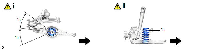
3. INSTALL REAR COIL SPRING
|
*a |
Identification Mark |
*b |
30° or less |
.png) |
Inner Side of the Vehicle |
- |
- |
(1) Set the rear coil spring to the rear No. 2 suspension arm assembly.
NOTICE:
- Set the rear coil spring so that its lower end is within the range shown in the illustration.
- Set the rear coil spring so that the identification mark is positioned as shown in the illustration.
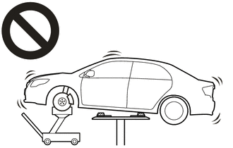
(2) Using a jack and wooden block, slowly jack up the rear No. 2 suspension arm assembly and then install the rear No. 2 suspension arm assembly to the rear axle carrier sub-assembly with the bolt and nut.
CAUTION:
- Do not raise the jack up too high.
- The vehicle could fall, resulting in a serious accident.
NOTICE:
- Tighten the bolt with the nut secured.
- When jacking up the rear No. 2 suspension arm assembly, be sure to jack it up slowly.
- Make sure to perform this operation with the vehicle kept as low as possible.
- Insert the bolt with the threaded end facing the front of the vehicle.
4. STABILIZE SUSPENSION
Click here .gif)
5. FULLY TIGHTEN REAR NO. 2 SUSPENSION ARM ASSEMBLY
|
|
for Rear Axle Carrier Sub-assembly Side: Click here |
6. INSTALL REAR STABILIZER LINK ASSEMBLY
|
|
Click here |
7. INSTALL REAR HEIGHT CONTROL SENSOR SUB-ASSEMBLY LH (for LH Side)
Click here
8. INSTALL REAR WHEEL
Click here
9. FULLY TIGHTEN REAR NO. 2 SUSPENSION ARM ASSEMBLY
|
|
for Rear Suspension Member Sub-assembly Side: Click here |
10. INSPECT AND ADJUST REAR WHEEL ALIGNMENT
Click here
11. PERFORM CALIBRATION (w/ Parking Assist Monitor System)
|
Parking assist monitor system |
|
|
Automatic headlight beam level control system |
|


