Toyota Corolla Cross: Installation
INSTALLATION
CAUTION / NOTICE / HINT
NOTICE:
This procedure includes the installation of small-head bolts. Refer to Small-Head Bolts of Basic Repair Hint to identify the small-head bolts.
Click here .gif)
CAUTION / NOTICE / HINT
COMPONENTS (INSTALLATION)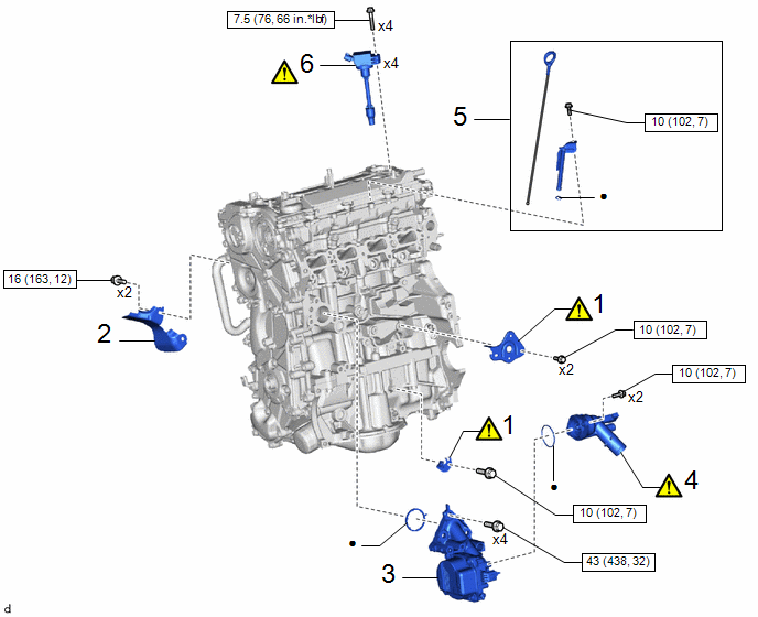
|
Procedure | Part Name Code |
.png) |
.png) |
 |
|---|---|---|---|---|---|
|
1 | WIRE HARNESS CLAMP BRACKET |
- |
|
- | - |
|
2 | NO. 3 EXHAUST MANIFOLD HEAT INSULATOR |
17169A | - |
- | - |
|
3 | ENGINE WATER PUMP ASSEMBLY (WATER INLET HOUSING) |
16032 | - |
- | - |
|
4 | WATER INLET WITH THERMOSTAT SUB-ASSEMBLY |
16031 |
|
- | - |
|
5 | ENGINE OIL LEVEL DIPSTICK GUIDE |
11452D | - |
- | - |
|
6 | IGNITION COIL ASSEMBLY |
19500 |
|
- | - |
.png) |
N*m (kgf*cm, ft.*lbf): Specified torque |
● | Non-reusable part |
|
Procedure | Part Name Code |
|
|
| |
|---|---|---|---|---|---|
|
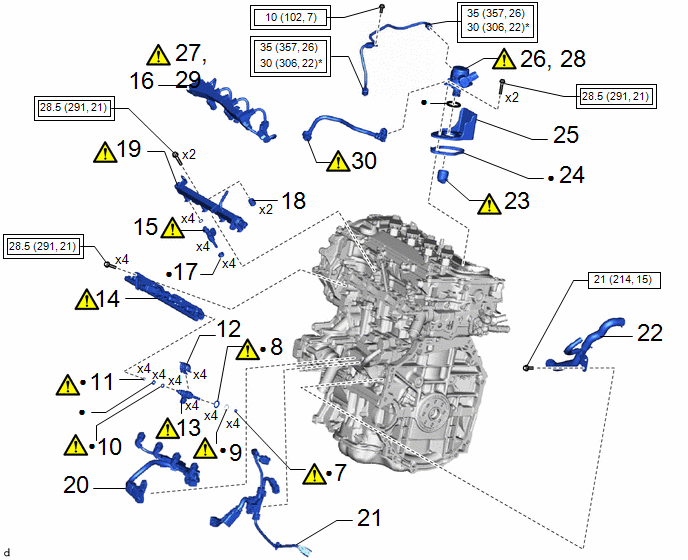
7 | INJECTOR SEAL |
23255A |
|
- | - |
|
8 | INJECTOR VIBRATION INSULATOR |
23291A |
|
- | - |
|
9 | C-RING |
- |
|
- | - |
|
10 | NO. 1 FUEL INJECTOR BACK-UP RING |
23256 |
|
- | - |
|
11 | NO. 3 FUEL INJECTOR BACK-UP RING |
23258 |
|
- | - |
|
12 | NOZZLE HOLDER CLAMP |
23695A | - |
- | - |
|
13 | DIRECT FUEL INJECTOR ASSEMBLY |
23250E |
|
- | - |
|
14 | FUEL DELIVERY PIPE |
23814B |
|
- | - |
|
15 | PORT FUEL INJECTOR ASSEMBLY |
23250F |
|
- | - |
|
16 | NO. 5 ENGINE WIRE |
82125N | - |
- | - |
|
17 | INJECTOR VIBRATION INSULATOR |
23291 | - |
- | - |
|
18 | FUEL DELIVERY SPACER |
23891 | - |
- | - |
|
19 | FUEL DELIVERY PIPE SUB-ASSEMBLY |
23807 |
|
- | - |
|
20 | NO. 6 ENGINE WIRE |
82126A | - |
- | - |
|
21 | SENSOR WIRE |
82219C | - |
- | - |
|
22 | WATER BY-PASS HOSE ASSEMBLY |
- | - |
- | - |
|
23 | FUEL PUMP LIFTER ASSEMBLY |
23470 |
|
- | - |
|
24 | FUEL PUMP SPACER GASKET |
23224D | - |
- | - |
|
25 | FUEL PUMP FLANGE |
23191 | - |
- | - |
|
26 | TEMPORARILY INSTALL FUEL (ENGINE ROOM SIDE) PUMP ASSEMBLY (for High Pressure) |
23100X |
|
- | - |
|
27 | TEMPORARILY INSTALL NO. 1 FUEL PIPE SUB-ASSEMBLY |
23801P |
|
- | - |
|
28 | INSTALL FUEL (ENGINE ROOM SIDE) PUMP ASSEMBLY (for High Pressure) |
23100X |
|
- | - |
|
29 | INSTALL NO. 1 FUEL PIPE SUB-ASSEMBLY |
23801P |
|
- | - |
|
30 | FUEL TUBE SUB-ASSEMBLY |
23910A |
|
- | - |
.png) |
Tightening torque for "Major areas involving basic vehicle performance such as moving/turning/stopping" : N*m (kgf*cm, ft.*lbf) |
|
N*m (kgf*cm, ft.*lbf): Specified torque |
|
● | Non-reusable part |
* | For use with SST |
|
Procedure | Part Name Code |
|
|
| |
|---|---|---|---|---|---|
|
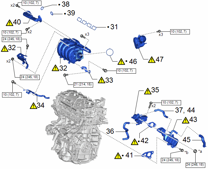
31 | NO. 1 INTAKE MANIFOLD TO HEAD GASKET |
17177 | - |
- | - |
|
32 | INTAKE MANIFOLD |
17111 |
|
- | - |
|
33 | INTAKE MANIFOLD STAY |
17138B |
|
- | - |
|
34 | NO. 3 WATER BY-PASS PIPE |
16279 |
|
- | - |
|
35 | EGR VALVE ASSEMBLY |
25620 |
|
- | - |
|
36 | NO. 8 WATER BY-PASS HOSE |
16296 | - |
- | - |
|
37 | NO. 4 WATER BY-PASS HOSE |
16281 | - |
- | - |
|
38 | EGR INLET GASKET |
25628 | - |
- | - |
|
39 | EGR VALVE ADAPTER GASKET |
25629 | - |
- | - |
|
40 | NO. 1 EGR PIPE SUB-ASSEMBLY |
25601 |
|
- | - |
|
41 | NO. 1 EGR COOLER GASKET |
25685 |
|
- | - |
|
42 | EGR VALVE GASKET |
25627 |
|
- | - |
|
43 | EGR COOLER ASSEMBLY |
25680 |
|
- | - |
|
44 | NO. 4 WATER BY-PASS HOSE |
16281 | - |
- | - |
|
45 | NO. 3 WATER BY-PASS HOSE |
16267 | - |
- | - |
|
46 | THROTTLE BODY GASKET |
22271 |
|
- | - |
|
47 | THROTTLE BODY WITH MOTOR ASSEMBLY |
22030 |
|
- | - |
|
*a | x2 or x3 |
*b | x3 or x2 |
|
|
N*m (kgf*cm, ft.*lbf): Specified torque |
● | Non-reusable part |
|
Procedure | Part Name Code |
|
|
| |
|---|---|---|---|---|---|
|
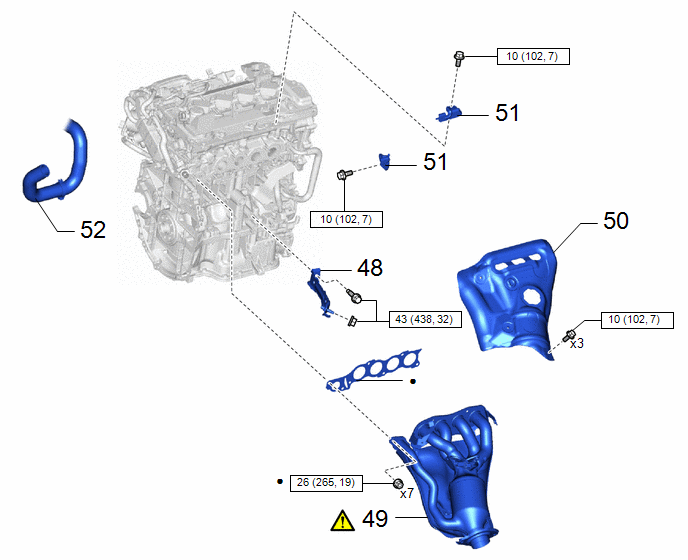
48 | MANIFOLD STAY |
17118 | - |
- | - |
|
49 | EXHAUST MANIFOLD |
17141 |
|
- | - |
|
50 | NO. 1 EXHAUST MANIFOLD HEAT INSULATOR |
17167 | - |
- | - |
|
51 | FUEL HOSE BRACKET |
23881B | - |
- | - |
|
52 | NO. 2 RADIATOR HOSE |
16572D | - |
- | - |
|
|
N*m (kgf*cm, ft.*lbf): Specified torque |
● | Non-reusable part |
PROCEDURE
1. INSTALL WIRE HARNESS CLAMP BRACKET
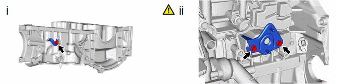
(1) Install the wire harness clamp bracket to the stiffening crankcase assembly with the bolt.
Torque:
10 N·m {102 kgf·cm, 7 ft·lbf}
(2) Using an 8 mm socket wrench, install the wire harness clamp bracket to the No. 1 ventilation case with the 2 bolts.
Torque:
10 N·m {102 kgf·cm, 7 ft·lbf}
2. INSTALL NO. 3 EXHAUST MANIFOLD HEAT INSULATOR
Torque:
16 N·m {163 kgf·cm, 12 ft·lbf}
3. INSTALL ENGINE WATER PUMP ASSEMBLY (WATER INLET HOUSING)
Torque:
43 N·m {438 kgf·cm, 32 ft·lbf}
4. INSTALL WATER INLET WITH THERMOSTAT SUB-ASSEMBLY
|
|
Click here |
5. INSTALL ENGINE OIL LEVEL DIPSTICK GUIDE
Torque:
10 N·m {102 kgf·cm, 7 ft·lbf}
6. INSTALL IGNITION COIL ASSEMBLY
|
|
Click here |
7. INSTALL FUEL INJECTOR SEAL
|
|
Click here |
8. INSTALL INJECTOR VIBRATION INSULATOR
|
|
Click here |
9. INSTALL C-RING
|
|
Click here |
10. INSTALL NO. 1 FUEL INJECTOR BACK-UP RING
|
|
Click here |
11. INSTALL NO. 3 FUEL INJECTOR BACK-UP RING
|
|
Click here |
12. INSTALL NOZZLE HOLDER CLAMP
Click here
13. INSTALL DIRECT FUEL INJECTOR ASSEMBLY
|
|
Click here |
14. INSTALL FUEL DELIVERY PIPE
|
|
Click here |
15. INSTALL PORT FUEL INJECTOR ASSEMBLY
|
|
Click here |
16. INSTALL NO. 5 ENGINE WIRE
Click here
17. INSTALL INJECTOR VIBRATION INSULATOR
Click here
18. INSTALL FUEL DELIVERY SPACER
Click here
19. INSTALL FUEL DELIVERY PIPE SUB-ASSEMBLY
|
|
Click here |
20. INSTALL NO. 6 ENGINE WIRE
Torque:
10 N·m {102 kgf·cm, 7 ft·lbf}
21. INSTALL SENSOR WIRE
Torque:
10 N·m {102 kgf·cm, 7 ft·lbf}
22. INSTALL WATER BY-PASS HOSE ASSEMBLY
Torque:
21 N·m {214 kgf·cm, 15 ft·lbf}
23. INSTALL FUEL PUMP LIFTER ASSEMBLY
|
|
Click here |
24. INSTALL FUEL PUMP SPACER GASKET
Click here
25. SET FUEL PUMP FLANGE
Click here
26. TEMPORARILY INSTALL FUEL (ENGINE ROOM SIDE) PUMP ASSEMBLY (for High Pressure)
|
|
Click here |
27. TEMPORARILY INSTALL NO. 1 FUEL PIPE SUB-ASSEMBLY
|
|
Click here |
28. INSTALL FUEL (ENGINE ROOM SIDE) PUMP ASSEMBLY (for High Pressure)
|
|
Click here |
29. INSTALL NO. 1 FUEL PIPE SUB-ASSEMBLY
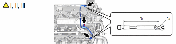
|
*a | 17 mm Union Nut Wrench |
*b | Torque Wrench Fulcrum Length |
(1) Using a 17 mm union nut wrench, tighten the union nut on the fuel delivery pipe side of the No. 1 fuel pipe sub-assembly.
Torque:
Specified tightening torque :
35 N·m {357 kgf·cm, 26 ft·lbf}
NOTICE:
Do not adjust the torque in the loosening direction.
HINT:
- Calculate the torque wrench reading when changing the fulcrum length of the torque wrench.
Click here
- When using a 17 mm union nut wrench (fulcrum length of 30 mm (1.18 in.)) + torque wrench (fulcrum length of 180 mm (7.09 in.)): 30 N*m (306 kgf*cm, 22 ft.*lbf)
(2) Using a 17 mm union nut wrench, tighten the union nut on the fuel pump assembly side of the No. 1 fuel pipe sub-assembly.
Torque:
Specified tightening torque :
35 N·m {357 kgf·cm, 26 ft·lbf}
NOTICE:
Do not adjust the torque in the loosening direction.
HINT:
- Calculate the torque wrench reading when changing the fulcrum length of the torque wrench.
Click here
- When using a 17 mm union nut wrench (fulcrum length of 30 mm (1.18 in.)) + torque wrench (fulcrum length of 180 mm (7.09 in.)): 30 N*m (306 kgf*cm, 22 ft.*lbf)
(3) Install the bolt.
Torque:
10 N·m {102 kgf·cm, 7 ft·lbf}
30. CONNECT FUEL TUBE SUB-ASSEMBLY
(a) Connect the fuel tube sub-assembly to the fuel delivery pipe with sensor assembly.
Click here
(b) Install the fuel pipe clamp to the fuel tube connector.
(c) Connect the fuel tube sub-assembly to the fuel pump assembly.
Click here
31. INSTALL NO. 1 INTAKE MANIFOLD TO HEAD GASKET
Click here
32. INSTALL INTAKE MANIFOLD
|
|
Click here |
33. INSTALL INTAKE MANIFOLD STAY
|
|
Click here |
34. INSTALL NO. 3 WATER BY-PASS PIPE
.png)
(1) Install the No. 3 water by-pass pipe to the water outlet and slide the clip to secure it.
(2) Using an 8 mm socket wrench, connect the No. 3 water by-pass pipe to the intake manifold with the bolt.
Torque:
10 N·m {102 kgf·cm, 7 ft·lbf}
35. INSTALL EGR VALVE ASSEMBLY
|
|
Click here |
36. CONNECT NO. 8 WATER BY-PASS HOSE
Click here
37. CONNECT NO. 4 WATER BY-PASS HOSE
Click here
38. INSTALL EGR INLET GASKET
Click here
39. INSTALL EGR VALVE ADAPTER GASKET
Click here
40. INSTALL NO. 1 EGR PIPE SUB-ASSEMBLY
|
|
Click here |
41. INSTALL NO. 1 EGR COOLER GASKET
|
|
Click here |
42. INSTALL EGR VALVE GASKET
|
|
Click here |
43. INSTALL EGR COOLER ASSEMBLY
|
|
Click here |
44. CONNECT NO. 4 WATER BY-PASS HOSE
|
|
Click here |
45. CONNECT NO. 3 WATER BY-PASS HOSE
|
|
Click here |
46. INSTALL THROTTLE BODY GASKET
|
|
Click here |
47. INSTALL THROTTLE BODY WITH MOTOR ASSEMBLY
|
|
Click here |
48. INSTALL MANIFOLD STAY
Click here
49. INSTALL EXHAUST MANIFOLD
|
|
Click here |
50. INSTALL NO. 1 EXHAUST MANIFOLD HEAT INSULATOR
Click here
51. INSTALL FUEL HOSE BRACKET
Torque:
10 N·m {102 kgf·cm, 7 ft·lbf}
52. CONNECT NO. 2 RADIATOR HOSE


