Toyota Corolla Cross: Installation
INSTALLATION
CAUTION / NOTICE / HINT
COMPONENTS (INSTALLATION)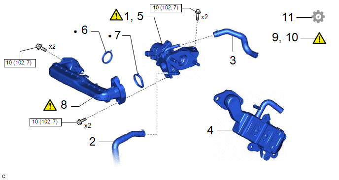
|
Procedure | Part Name Code |
.png) |
.png) |
 |
|---|---|---|---|---|---|
|
1 | SET EGR VALVE ASSEMBLY |
25620 |
|
- | - |
|
2 | NO. 8 WATER BY-PASS HOSE |
16296 | - |
- | - |
|
3 | NO. 4 WATER BY-PASS HOSE |
16281 | - |
- | - |
|
4 | EGR COOLER ASSEMBLY |
25680 | - |
- | - |
|
5 | INSTALL EGR VALVE ASSEMBLY |
25620 |
|
- | - |
|
6 | EGR INLET GASKET |
25628 | - |
- | - |
|
7 | EGR VALVE ADAPTER GASKET |
25629 | - |
- | - |
|
8 | NO. 1 EGR PIPE SUB-ASSEMBLY |
25601 |
|
- | - |
|
9 | INSPECT FOR COOLANT LEAK |
- |
|
- | - |
|
10 | INSPECT FOR EXHAUST GAS LEAK |
- |
|
- | - |
|
11 | PERFORM INITIALIZATION |
- | - |
- |
|
.png) |
N*m (kgf*cm, ft.*lbf): Specified torque |
● | Non-reusable part |
CAUTION / NOTICE / HINT
NOTICE:
This procedure includes the installation of small-head bolts. Refer to Small-Head Bolts of Basic Repair Hint to identify the small-head bolts.
Click here .gif)
PROCEDURE
1. SET EGR VALVE ASSEMBLY
|
|
NOTICE: Perform "Inspection After Repair" after replacing the EGR valve assembly. Click here |
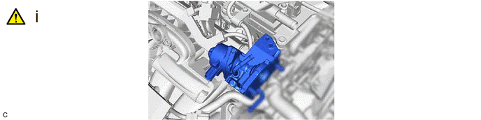
(1) Set the EGR valve assembly to the camshaft housing.
HINT:
At this time, do not install the parts with bolts.
2. CONNECT NO. 8 WATER BY-PASS HOSE
3. CONNECT NO. 4 WATER BY-PASS HOSE
4. INSTALL EGR COOLER ASSEMBLY
Click here
5. INSTALL EGR VALVE ASSEMBLY
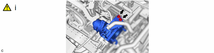
(1) Using the 8 mm socket wrench, install the EGR valve assembly with the 2 bolts.
Torque:
10 N·m {102 kgf·cm, 7 ft·lbf}
6. INSTALL EGR INLET GASKET
7. INSTALL EGR VALVE ADAPTER GASKET
8. INSTALL NO. 1 EGR PIPE SUB-ASSEMBLY
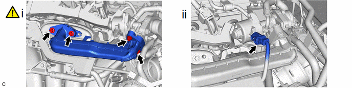
(1) Using an 8 mm socket wrench, install the No. 1 EGR pipe sub-assembly to the intake manifold and EGR valve assembly with the 4 bolts.
Torque:
10 N·m {102 kgf·cm, 7 ft·lbf}
(2) Connect the EGR valve assembly connector.
9. INSPECT FOR COOLANT LEAK
Click here
10. INSPECT FOR EXHAUST GAS LEAK
Click here
11. PERFORM INITIALIZATION
(a) Perform "Inspection After Repair" after replacing the EGR valve assembly.
Click here


