Toyota Corolla Cross: Installation
INSTALLATION
CAUTION / NOTICE / HINT
COMPONENTS (INSTALLATION)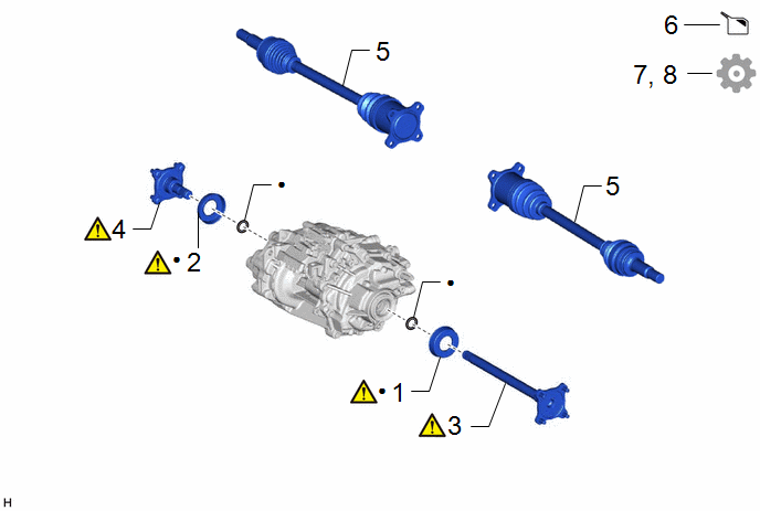
|
Procedure |
Part Name Code |
.png) |
.png) |
.png) |
|
|---|---|---|---|---|---|
|
1 |
DIFFERENTIAL SIDE GEAR SHAFT DUST COVER LH |
41336M |
|
- |
- |
|
2 |
DIFFERENTIAL SIDE GEAR SHAFT DUST COVER RH |
41336L |
|
- |
- |
|
3 |
DIFFERENTIAL SIDE GEAR SHAFT SUB-ASSEMBLY LH |
41309L |
|
- |
- |
|
4 |
DIFFERENTIAL SIDE GEAR SHAFT SUB-ASSEMBLY RH |
41309K |
|
- |
- |
|
5 |
REAR DRIVE SHAFT ASSEMBLY |
- |
- |
- |
- |
|
6 |
ADD HYBRID TRANSAXLE FLUID |
- |
- |
|
- |
|
7 |
INSPECT HYBRID TRANSAXLE FLUID |
- |
- |
- |
|
|
8 |
INSPECT FOR HYBRID TRANSAXLE FLUID LEAK |
- |
- |
- |
|
|
● |
Non-reusable part |
- |
- |
PROCEDURE
1. INSTALL DIFFERENTIAL SIDE GEAR SHAFT DUST COVER LH
|
|
NOTICE:
|

|
*a |
Press |
*b |
Steel Plate |
(1) Using SST, a steel plate and press, install a new differential side gear shaft dust cover LH to the differential side gear shaft sub-assembly LH.
SST: 09316-20011
SST: 09527-20011
2. INSTALL DIFFERENTIAL SIDE GEAR SHAFT DUST COVER RH
3. INSTALL DIFFERENTIAL SIDE GEAR SHAFT SUB-ASSEMBLY LH
|
*a |
Less than 421.1 mm (1.38 ft.) |
- |
- |
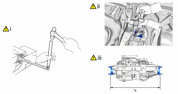
(1) Using a brass bar and hammer, install a new snap ring to the differential side gear shaft sub-assembly LH.
(2) Using SST, install the differential side gear shaft sub-assembly LH to the rear traction motor with transaxle assembly.
SST: 09520-24010
09520-04010
09520-32040
NOTICE:
- Position the snap ring with its end gap facing downward.
- Do not install the differential side gear shaft sub-assembly LH at an angle. If the differential side gear shaft sub-assembly LH is installed at an angle, replace the snap ring with a new one.
- Do not damage the differential side gear shaft LH type T oil seal.
(3) Measure the distance between the right differential side gear shaft sub-assembly and left differential side gear shaft sub-assembly as shown in the illustration.
Standard Distance:
Less than 471.4 mm (1.55 ft.)
4. INSTALL DIFFERENTIAL SIDE GEAR SHAFT SUB-ASSEMBLY RH
5. INSTALL REAR DRIVE SHAFT ASSEMBLY
Click here .gif)
6. ADD HYBRID TRANSAXLE FLUID
Click here
7. INSPECT HYBRID TRANSAXLE FLUID
Click here
8. INSPECT FOR HYBRID TRANSAXLE FLUID LEAK
Click here


