Toyota Corolla Cross: Installation
INSTALLATION
CAUTION / NOTICE / HINT
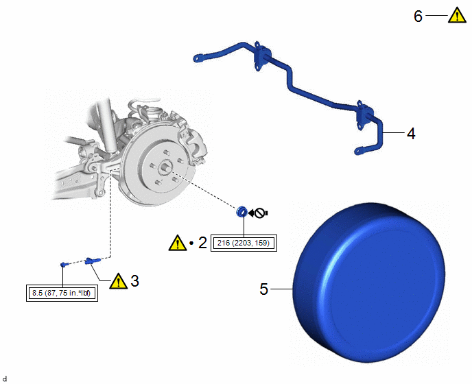
COMPONENTS (INSTALLATION)
|
Procedure |
Part Name Code |
.png) |
.png) |
.png) |
|
|---|---|---|---|---|---|
|
1 |
REAR DRIVE SHAFT ASSEMBLY |
42340B |
|
- |
- |
.png) |
Tightening torque for "Major areas involving basic vehicle performance such as moving/turning/stopping": N*m (kgf*cm, ft.*lbf) |
.png) |
Do not apply lubricants to the threaded parts |

|
Procedure |
Part Name Code |
.png) |
.png) |
.png) |
|
|---|---|---|---|---|---|
|
2 |
REAR AXLE SHAFT NUT |
42312B |
|
- |
- |
|
3 |
REAR SKID CONTROL SENSOR |
89544E |
|
- |
- |
|
4 |
REAR STABILIZER BAR |
48812 |
- |
- |
- |
|
5 |
REAR WHEELS |
- |
- |
- |
- |
|
6 |
CHECK FOR SPEED SENSOR SIGNAL |
- |
|
- |
- |
CAUTION / NOTICE / HINT
.png) |
Tightening torque for "Major areas involving basic vehicle performance such as moving/turning/stopping": N*m (kgf*cm, ft.*lbf) |
● |
Non-reusable part |
.png) |
Do not apply lubricants to the threaded parts |
- |
- |
HINT:
- Use the same procedure for the RH side and LH side.
- The following procedure is for the LH side.
PROCEDURE
1. INSTALL REAR DRIVE SHAFT ASSEMBLY

|
*a |
Matchmark |
- |
- |
(1) Align the matchmarks and install the rear drive shaft assembly to the rear axle hub and bearing assembly.
NOTICE:
- Do not damage the rear drive shaft outboard joint boot.
- Check that there is no foreign matter on the contact surfaces.
(2) Align the matchmarks on the rear drive shaft assembly and differential side gear shaft sub-assembly.
NOTICE:
Do not damage the rear drive shaft inboard joint boot.
(3) Install the 4 nuts and 4 washers.
Torque:
56 N·m {571 kgf·cm, 41 ft·lbf}
2. INSTALL REAR AXLE SHAFT NUT
.png)
(1) Clean the threaded parts on the rear drive shaft assembly and a new rear axle shaft nut using non-residue solvent.
NOTICE:
- Be sure to perform this work even when using a new rear drive shaft assembly.
- Keep the threaded parts free of oil and foreign matter.
(2) Using a 30 mm deep socket wrench, install the rear axle shaft nut while applying the brakes.
Torque:
216 N·m {2203 kgf·cm, 159 ft·lbf}
(3) Using a chisel and a hammer, stake the rear axle shaft nut.
3. INSTALL REAR SKID CONTROL SENSOR
.png) |
Click here |
4. INSTALL REAR STABILIZER BAR
Click here .gif)
5. INSTALL REAR WHEELS
Click here .gif)
6. CHECK FOR SPEED SENSOR SIGNAL
Click here .gif)


