Toyota Corolla Cross: Installation
INSTALLATION
CAUTION / NOTICE / HINT
COMPONENTS (INSTALLATION)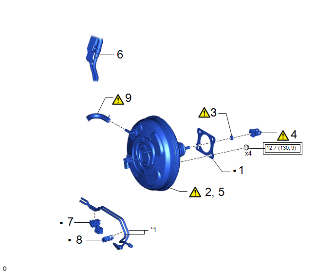
|
Procedure |
Part Name Code |
.png) |
.png) |
.png) |
|
|---|---|---|---|---|---|
|
1 |
BRAKE BOOSTER GASKET |
44785 |
- |
- |
- |
|
2 |
TEMPORARILY INSTALL BRAKE BOOSTER ASSEMBLY |
44610 |
|
- |
- |
|
3 |
CLEVIS LOCK NUT |
- |
|
- |
- |
|
4 |
BRAKE MASTER CYLINDER PUSH ROD CLEVIS |
47264D |
|
- |
- |
|
5 |
INSTALL BRAKE BOOSTER ASSEMBLY |
44610 |
|
- |
- |
|
6 |
FUEL TUBE |
- |
- |
- |
- |
|
7 |
NO. 4 BRAKE TUBE CLAMP |
47374B |
- |
- |
- |
|
8 |
NO. 5 BRAKE TUBE CLAMP |
47375 |
- |
- |
- |
|
9 |
CHECK VALVE TO CONNECTOR TUBE HOSE |
- |
|
- |
- |
|
*1 |
BRAKE LINE |
- |
- |
.png) |
Tightening torque for "Major areas involving basic vehicle performance such as moving/turning/stopping" : N*m (kgf*cm, ft.*lbf) |
● |
N*m (kgf*cm, ft.*lbf): Specified torque |
|
Procedure |
Part Name Code |
|
|
|
|
|---|---|---|---|---|---|
|
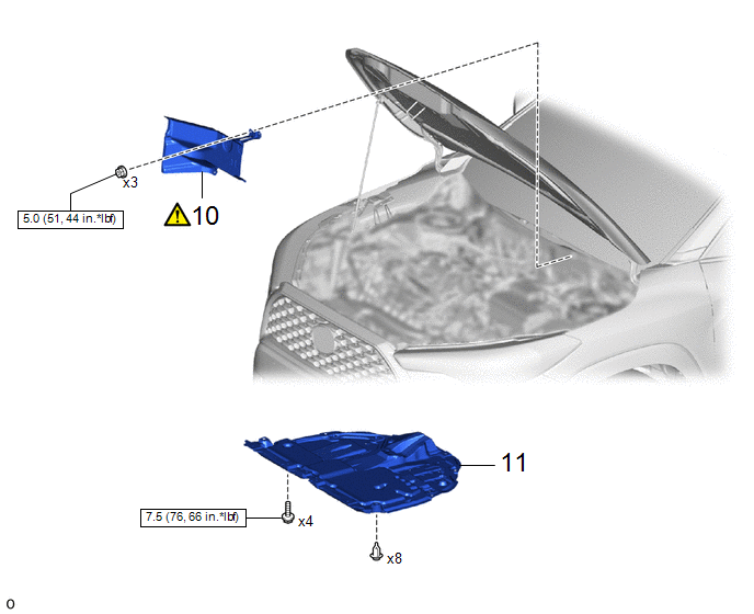
10 |
DASH PANEL HEAT INSULATOR |
55225C |
|
- |
- |
|
11 |
NO. 1 ENGINE UNDER COVER ASSEMBLY |
51410 |
- |
- |
- |
.png) |
N*m (kgf*cm, ft.*lbf): Specified torque |
- |
- |
|
Procedure |
Part Name Code |
|
|
|
|
|---|---|---|---|---|---|
|
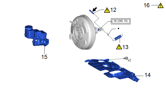
12 |
PUSH ROD PIN |
47264A |
|
- |
- |
|
13 |
BRAKE PEDAL RETURN SPRING |
47101A |
|
- |
- |
|
14 |
NO. 1 INSTRUMENT PANEL UNDER COVER SUB-ASSEMBLY |
55606 |
- |
- |
- |
|
15 |
BRAKE MASTER CYLINDER SUB-ASSEMBLY |
47201 |
- |
- |
- |
|
16 |
INSPECT AND ADJUST BRAKE PEDAL |
- |
|
- |
- |
|
|
Tightening torque for "Major areas involving basic vehicle performance such as moving/turning/stopping" : N*m (kgf*cm, ft.*lbf) |
● |
Non-reusable part |
.png) |
Lithium soap base glycol grease |
- |
- |
PROCEDURE
1. INSTALL BRAKE BOOSTER GASKET
2. TEMPORARILY INSTALL BRAKE BOOSTER ASSEMBLY
|
|
NOTICE: Do not apply excessive force to the brake lines. |
3. TEMPORARILY INSTALL CLEVIS LOCK NUT
|
|
NOTICE: Fully tighten the lock nut when adjusting the brake pedal height. |
4. TEMPORARILY INSTALL BRAKE MASTER CYLINDER PUSH ROD CLEVIS
|
|
NOTICE: Fully tighten the lock nut when adjusting the brake pedal height. |
5. INSTALL BRAKE BOOSTER ASSEMBLY
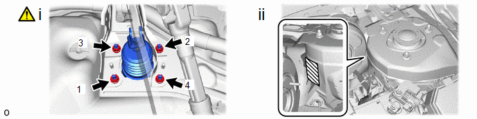
(1) Install the 4 nuts to secure the brake booster assembly.
Torque:
12.7 N·m {130 kgf·cm, 9 ft·lbf}
NOTICE:
Tighten the 4 nuts in the order shown in the illustration.
(2) Remove the protective tape.
6. INSTALL FUEL TUBE
7. INSTALL NO. 4 BRAKE TUBE CLAMP
8. INSTALL NO. 5 BRAKE TUBE CLAMP
9. CONNECT CHECK VALVE TO CONNECTOR TUBE HOSE
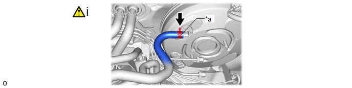
|
*a |
Paint Mark |
- |
- |
(1) Connect the check valve to connector tube hose to the brake booster assembly and slide the clip to secure it.
NOTICE:
- When connecting the check valve to connector tube hose, face the paint mark up.
- Make sure that the tabs of the clip are facing upward.
10. INSTALL DASH PANEL HEAT INSULATOR
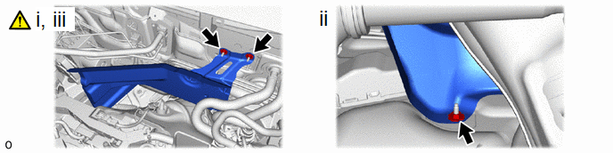
(1) Temporarily install the dash panel heat insulator to the vehicle body with the 2 nuts.
(2) Install the nut.
Torque:
5.0 N·m {51 kgf·cm, 44 in·lbf}
(3) Tighten the 2 nuts.
Torque:
5.0 N·m {51 kgf·cm, 44 in·lbf}
11. INSTALL NO. 1 ENGINE UNDER COVER ASSEMBLY
Click here .gif)
12. INSTALL PUSH ROD PIN
|
|
Click here |
13. INSTALL BRAKE PEDAL RETURN SPRING
|
|
Click here |
14. INSTALL NO. 1 INSTRUMENT PANEL UNDER COVER SUB-ASSEMBLY
15. INSTALL BRAKE MASTER CYLINDER SUB-ASSEMBLY
Click here
16. INSPECT AND ADJUST BRAKE PEDAL
Click here


