Toyota Corolla Cross: Installation
INSTALLATION
CAUTION / NOTICE / HINT
COMPONENTS (INSTALLATION)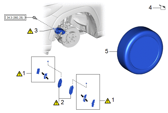
|
Procedure |
Part Name Code |
.png) |
.png) |
.png) |
|
|---|---|---|---|---|---|
|
1 |
FRONT ANTI SQUEAL SHIM KIT |
04945 |
|
- |
- |
|
2 |
FRONT DISC BRAKE PAD KIT |
04465 |
|
- |
- |
|
3 |
FRONT DISC BRAKE CYLINDER ASSEMBLY |
- |
|
- |
- |
|
4 |
INSPECT BRAKE FLUID LEVEL IN RESERVOIR |
- |
- |
|
- |
|
5 |
FRONT WHEEL |
- |
- |
- |
- |
.png) |
Tightening torque for "Major areas involving basic vehicle performance such as moving/turning/stopping": N*m (kgf*cm, ft.*lbf) |
.png) |
Disc brake grease |
CAUTION / NOTICE / HINT
NOTICE:
- Immediately after installing the brake pads, the braking performance may be reduced. Always perform a road test in a safe place while paying attention to the surroundings.
- After replacing the front disc brake pads, the brake pedal may feel soft due to clearance between the front disc brake pads and front disc. Depress the brake pedal several times until the brake pedal feels firm.
- After replacing the front disc brake pads, always perform a road test to check the braking performance and check for vibrations.
HINT:
- Use the same procedure for the RH side and LH side.
- The following procedure is for the LH side.
PROCEDURE
1. INSTALL FRONT ANTI SQUEAL SHIM KIT
|
|
NOTICE:
|
|
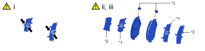
*1 |
Front No. 1 Disc Brake Anti-squeal Shim |
*2 |
Front No. 2 Disc Brake Anti-squeal Shim |
|
*3 |
Front Disc Brake Pad Wear Indicator Plate |
- |
- |
|
|
Disc Brake Grease |
- |
- |
(1) Apply disc brake grease to both sides of each front No. 1 disc brake anti-squeal shim as shown in the illustration.
(2) Install the front No. 1 disc brake anti-squeal shim and front No. 2 disc brake anti-squeal shim to each front disc brake pad.
(3) Install the front disc brake pad wear indicator plate to each front disc brake pad.
2. INSTALL FRONT DISC BRAKE PAD KIT
|
|
CAUTION:
|
.png)
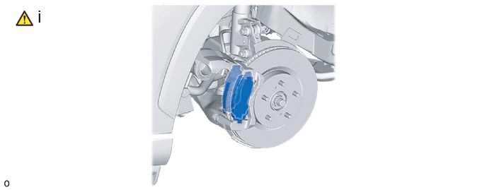
(1) Install the 2 front disc brake pads to the front disc brake cylinder mounting.
NOTICE:
- Keep the friction surfaces of the front disc brake pads and front disc free from oil and grease.
- Install the front disc brake pad so that the pad wear indicator plate is mounted on the upper side of the vehicle.
3. INSTALL FRONT DISC BRAKE CYLINDER ASSEMBLY
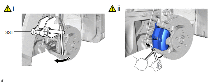
(1) Using SST, push back the front disc brake piston.
SST: 09719-77020
NOTICE:
- Make sure the brake fluid does not overflow from the reservoir.
- Do not forcibly push in the rear disc brake piston.
(2) Hold the front disc brake cylinder shide pin (lower side) and install the front disc brake cylinder assembly to the front disc brake cylinder mounting with the bolt.
Torque:
34.3 N·m {350 kgf·cm, 25 ft·lbf}
(3) Depress the brake pedal several times.
4. INSPECT BRAKE FLUID LEVEL IN RESERVOIR
- for HEV Model:
Click here
.gif)
- for Gasoline Model:
Click here
5. INSTALL FRONT WHEEL
Click here


