Toyota Corolla Cross: Inspection
INSPECTION
PROCEDURE
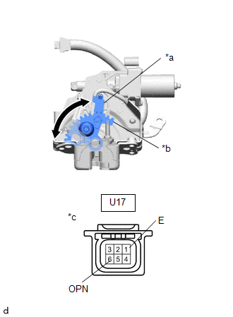
1. INSPECT BACK DOOR LOCK WITH COURTESY LIGHT SWITCH (w/o Power Back Door)
| (a) Check the operation of the door lock motor. (1) Move the back door lock with courtesy light switch assembly to the lock position. (2) Apply auxiliary battery voltage to the back door lock with courtesy light switch assembly and check the operation of the door lock motor. OK:
If the result is not as specified, replace the back door lock with courtesy light switch assembly. |
|
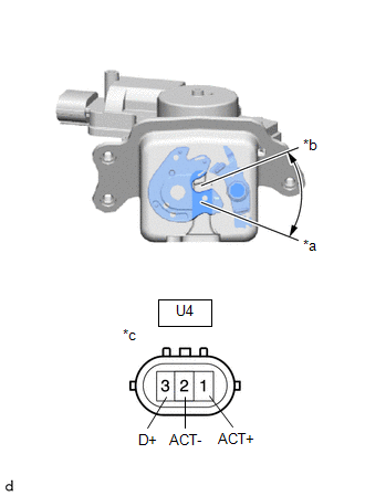
(b) Check the operation of the door courtesy switch.
(1) Measure the resistance according to the value(s) in the table below.
Standard Resistance:
|
Tester Connection | Condition |
Specified Condition |
|---|---|---|
|
U4-2 (ACT-) - U4-3 (D+) |
Lock | 10 kΩ or higher |
|
Unlock | Below 1 Ω |
If the result is not as specified, replace the back door lock with courtesy light switch assembly.
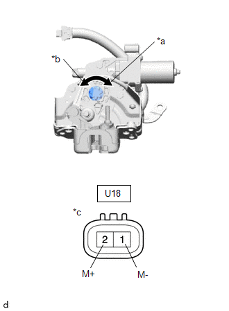
2. INSPECT BACK DOOR LOCK WITH COURTESY LIGHT SWITCH (w/ Power Back Door)
| (a) Check the operation of the door lock motor. (1) Apply auxiliary battery voltage to the back door lock with courtesy light switch assembly and check the operation of the door lock motor. OK:
If the result is not as specified, replace the back door lock with courtesy light switch assembly. |
|
| (b) Check the operation of the latch switch. (1) Measure the resistance according to the value(s) in the table below. Standard Resistance
If the result is not as specified, replace the back door lock with courtesy light switch assembly. |
|
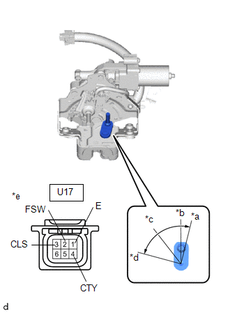
(c) Check the operation of the pawl switch.
(1) Measure the resistance according to the value(s) in the table below.
Standard Resistance|
Tester Connection | Condition |
Specified Condition |
|---|---|---|
|
U17-2 (FSW) - U17-1 (E) |
Open-latch | 10 kΩ or higher |
|
Open-latch → Half-latch |
10 kΩ or higher → Below 1 Ω → 10 kΩ or higher | |
|
Half-latch | 10 kΩ or higher | |
|
Half-latch → Full-latch |
10 kΩ or higher → Below 1 Ω → 10 kΩ or higher | |
|
Full-latch | 10 kΩ or higher |
If the result is not as specified, replace the back door lock with courtesy light switch assembly.
(d) Check the operation of the back door courtesy switch.
(1) Measure the resistance according to the value(s) in the table below.
Standard Resistance|
Tester Connection | Condition |
Specified Condition |
|---|---|---|
|
U17-4 (CTY) - U17-1 (E) |
Open-latch |
Below 1 Ω |
|
Half-latch | ||
|
Half-latch → Full-latch |
Below 1 Ω → 10 kΩ or higher | |
|
Full-latch |
10 kΩ or higher | |
|
Over-latch |
If the result is not as specified, replace the back door lock with courtesy light switch assembly.
| (e) Check the operation of the selector switch. (1) Measure the resistance according to the value(s) in the table below. Standard Resistance
If the result is not as specified, replace the back door lock with courtesy light switch assembly. |
|