Toyota Corolla Cross: Inspection
INSPECTION
PROCEDURE
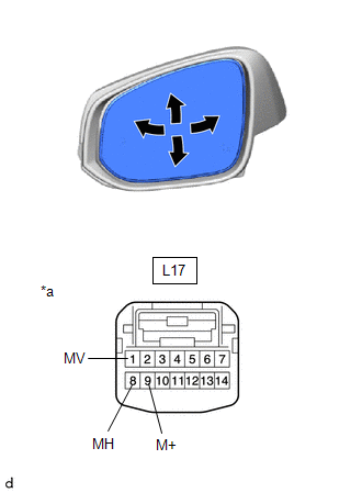
1. INSPECT OUTER REAR VIEW MIRROR ASSEMBLY LH
(a) Check the operation of the mirror surface.
NOTICE:
If the mirror surface is fully turned to the right, left, upward or downward position, the motor slips and produces a clicking noise. This is not a malfunction.
| (1) Apply auxiliary battery voltage and check the operation of the mirror surface. OK:
If the result is not as specified, replace the outer rear view mirror assembly LH. |
|
(b) Check the operation of the mirror heater.
| (1) Measure the resistance according to the value(s) in the table below. Standard Resistance:
If the result is not as specified, inspect the outer mirror LH or replace the outer rear view mirror assembly LH. |
|
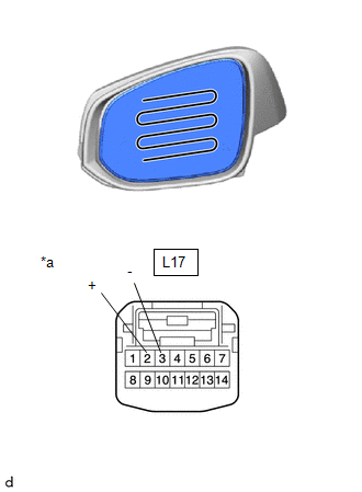
(2) Connect a cable from the positive (+) auxiliary battery terminal to L17-2 (+) and negative (-) auxiliary battery terminal to L17-3 (-), then check that the mirror becomes warm.
HINT:
It takes a short time for the mirror to become warm.
OK:
Mirror becomes warm.
If the result is not as specified, inspect the outer mirror LH or replace the outer rear view mirror assembly LH.
(c) Check the side turn signal light assembly LH. (w/ Side Turn Signal Light)
| (1) Apply auxiliary battery voltage to the terminals of the connector, and check the illumination condition. OK:
If the result is not as specified, inspect the side turn signal light assembly LH or replace the outer rear view mirror assembly LH. |
|
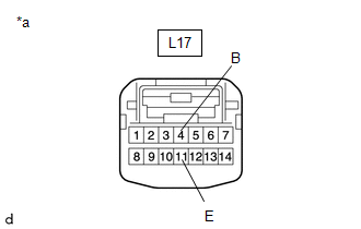
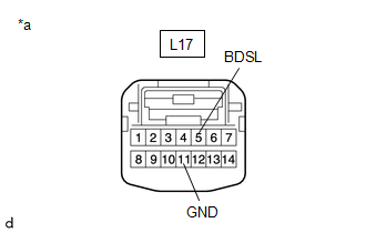
(d) Check the operation of the blind spot monitor indicator. (w/ Blind Spot Monitor System)
(1) Connect 4 new 1.5 V dry-cell batteries in series.
| (2) Apply 6 V dry-cell battery voltage to the terminals of the connector, and check the blind spot monitor indicator condition. NOTICE: Do not apply a voltage of 6 V or higher. OK:
If the result is not as specified, inspect the outer mirror LH or replace the outer rear view mirror assembly LH. |
|
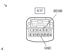
2. INSPECT OUTER REAR VIEW MIRROR ASSEMBLY RH
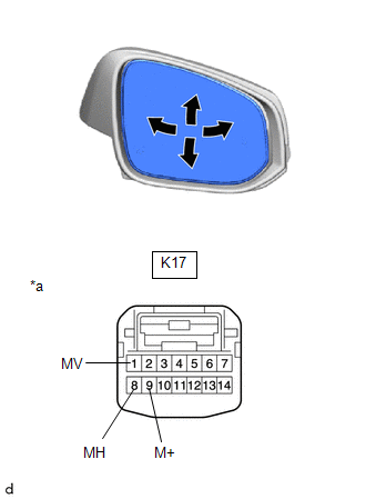
(a) Check the operation of the mirror surface.
NOTICE:
If the mirror surface is fully turned to the right, left, upward or downward position, the motor slips and produces a clicking noise. This is not a malfunction.
| (1) Apply auxiliary battery voltage and check the operation of the mirror surface. OK:
If the result is not as specified, replace the outer rear view mirror assembly RH. |
|
(b) Check the operation of the mirror heater.
| (1) Measure the resistance according to the value(s) in the table below. Standard Resistance:
If the result is not as specified, inspect the outer mirror RH or replace the outer rear view mirror assembly RH. |
|
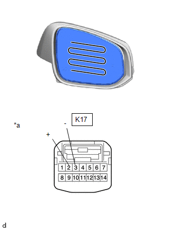
(2) Connect a cable from the positive (+) auxiliary battery terminal to K17-2 (+) and negative (-) auxiliary battery terminal to K17-3 (-), then check that the mirror becomes warm.
HINT:
It takes a short time for the mirror to become warm.
OK:
Mirror becomes warm.
If the result is not as specified, inspect the outer mirror RH or replace the outer rear view mirror assembly RH.
(c) Check the side turn signal light assembly RH. (w/ Side Turn Signal Light)
| (1) Apply auxiliary battery voltage to the terminals of the connector, and check the illumination condition. OK:
If the result is not as specified, inspect the side turn signal light assembly RH or replace the outer rear view mirror assembly RH. |
|
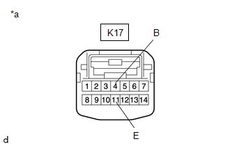
(d) Check the operation of the blind spot monitor indicator. (w/ Blind Spot Monitor System)
(1) Connect 4 new 1.5 V dry-cell batteries in series.
| (2) Apply 6 V dry-cell battery voltage to the terminals of the connector, and check the blind spot monitor indicator condition. NOTICE: Do not apply a voltage of 6 V or higher. OK:
If the result is not as specified, inspect the outer mirror RH or replace the outer rear view mirror assembly RH. |
|