Toyota Corolla Cross Owners & Service Manuals

Toyota Corolla Cross: Inspection

INSPECTION

PROCEDURE

1. INSPECT OUTER MIRROR SWITCH ASSEMBLY

(a) Check the mirror select and surface adjust switch.

(1) Turn the mirror select and surface adjust switch to the L position.

(2) Measure the resistance according to the value(s) in the table below.

Standard Resistance (for left side):

Tester Connection

Condition

Specified Condition

L11-6 (B) - L11-2 (VL)

L11-7 (E) - L11-11 (M+)

Up

Below 1 Ω

L11-6 (B) - L11-2 (VL)

L11-7 (E) - L11-11 (M+)

Off

10 kΩ or higher

L11-6 (B) - L11-11 (M+)

L11-7 (E) - L11-2 (VL)

Down

Below 1 Ω

L11-6 (B) - L11-11 (M+)

L11-7 (E) - L11-2 (VL)

Off

10 kΩ or higher

L11-6 (B) - L11-4 (HL)

L11-7 (E) - L11-11 (M+)

Left

Below 1 Ω

L11-6 (B) - L11-4 (HL)

L11-7 (E) - L11-11 (M+)

Off

10 kΩ or higher

L11-6 (B) - L11-11 (M+)

L11-7 (E) - L11-4 (HL)

Right

Below 1 Ω

L11-6 (B) - L11-11 (M+)

L11-7 (E) - L11-4 (HL)

Off

10 kΩ or higher

*a

Mirror Select and Surface Adjust Switch

*b

Component without harness connected

(Outer Mirror Switch Assembly)

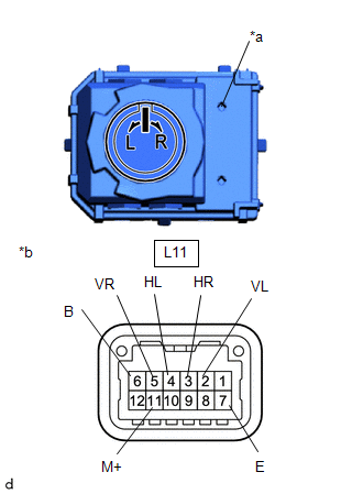
(3) Turn the mirror select and surface adjust switch to the R position.

(4) Measure the resistance according to the value(s) in the table below.

Standard Resistance (for right side):

Tester Connection

Condition

Specified Condition

L11-6 (B) - L11-5 (VR)

L11-7 (E) - L11-11 (M+)

Up

Below 1 Ω

L11-6 (B) - L11-5 (VR)

L11-7 (E) - L11-11 (M+)

Off

10 kΩ or higher

L11-6 (B) - L11-11 (M+)

L11-7 (E) - L11-5 (VR)

Down

Below 1 Ω

L11-6 (B) - L11-11 (M+)

L11-7 (E) - L11-5 (VR)

Off

10 kΩ or higher

L11-6 (B) - L11-3 (HR)

L11-7 (E) - L11-11 (M+)

Left

Below 1 Ω

L11-6 (B) - L11-3 (HR)

L11-7 (E) - L11-11 (M+)

Off

10 kΩ or higher

L11-6 (B) - L11-11 (M+)

L11-7 (E) - L11-3 (HR)

Right

Below 1 Ω

L11-6 (B) - L11-11 (M+)

L11-7 (E) - L11-3 (HR)

Off

10 kΩ or higher

If the result is not as specified, replace the outer mirror switch assembly.

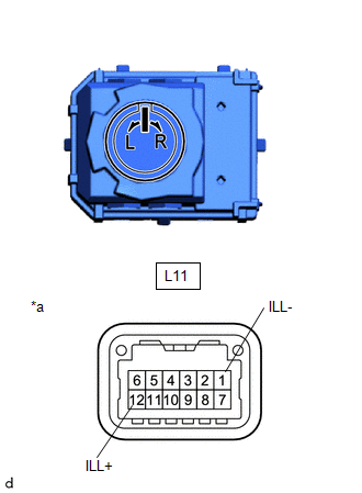
(b) Check that the LED illuminates.

(1) Apply auxiliary battery voltage to the terminals of the connector, and check that the LED illuminates.

OK:

Tester Connection

Specified Condition

L11-12 (ILL+) - Auxiliary battery positive (+)

L11-1 (ILL-) - Auxiliary battery negative (-)

LED illuminates

If the result is not as specified, replace the outer mirror switch assembly.

*a

Component without harness connected

(Outer Mirror Switch Assembly)

    READ NEXT:

     Installation

    INSTALLATION CAUTION / NOTICE / HINT COMPONENTS (INSTALLATION) Procedure Part Name Code 1 OUTER MIRROR SWITCH ASSEMBLY 84870A - - - 2 MULTIPLEX

     Outer Rear View Mirror

     Removal

    REMOVAL CAUTION / NOTICE / HINT COMPONENTS (REMOVAL) Procedure Part Name Code 1 FRONT DOOR INSIDE HANDLE BEZEL PLUG 69284F - - 2 DOOR ASSI

    SEE MORE:

     Removal

    REMOVAL CAUTION / NOTICE / HINT COMPONENTS (REMOVAL) Procedure Part Name Code 1 PRECAUTION - - - 2 CABLE FROM NEGATIVE AUXILIARY BATTERY TERMINAL - - - - 3 REAR CENTER SEAT OUTER BELT ASSEMBLY 733

     Problem Symptoms Table

    PROBLEM SYMPTOMS TABLE HINT: Use the table below to help determine the cause of problem symptoms. If multiple suspected areas are listed, the potential causes of the symptoms are listed in order of probability in the "Suspected Area" column of the table. Check each symptom by check

    © 2020-2024 Copyright www.tcorollacross.com