Toyota Corolla Cross: Inspection
INSPECTION
PROCEDURE
1. INSPECT TIRES
(a) Inspect the tires for wear and proper inflation pressure.
Cold Tire Inflation Pressure:
|
Tire Size |
Cold Tire Inflation Pressure |
|
|---|---|---|
|
Front |
Rear |
|
| *1: for 2WD
*2: for AWD |
||
|
215/65R17 99H |
230 kPa (2.3 kgf/cm2, 33 psi) |
200 kPa (2.0 kgf/cm2, 29 psi)*1 230 kPa (2.3 kgf/cm2, 33 psi)*2 |
|
225/55R18 98V |
230 kPa (2.3 kgf/cm2, 33 psi) |
210 kPa (2.1 kgf/cm2, 30 psi)*1 230 kPa (2.3 kgf/cm2, 33 psi)*2 |
|
225/50RF18 95V |
230 kPa (2.3 kgf/cm2, 33 psi) |
230 kPa (2.3 kgf/cm2, 33 psi) |
Cold Tire Inflation Pressure (for Compact Spare Tire):
|
Tire Size |
Cold Tire Inflation Pressure |
|---|---|
|
T155/80D17 101M |
420 kPa (4.2 kgf/cm2, 60 psi) |
(1) Perform initialization. (w/ Tire Pressure Warning System)
Click here .gif)
(2) Tire pressure adjustment method when warm (w/ Tire Pressure Warning System):
- Turn the ignition switch off.
- Connect the GTS to the DLC3.
- Turn the ignition switch to ON.
- Turn the GTS on.
- Enter the following menus: Chassis / Tire Pressure Monitor / Data List.
- Adjust the tire pressure so that the displayed value is equal to the set pressure.
- Perform initialization and check that initialization completes.
Click here
.gif)
- Check and record the value of the Data List item "Temperature in Tire". (Ts)
- Check and record the ambient temperature during tire pressure adjustment. (Tm)
- Readjust the tire pressure according to the difference between the tire
internal temperature (Ts) and the ambient temperature (Tm). (P)
HINT:
Tire internal temperature: Ts, Ambient temperature: Tm, Tire pressure readjustment value: P
P = (Specified Pressure) + (Ts - Tm)
- Check the pressure adjustment value with the Data List item "Tire Inflation Pressure".
|
Tester Display |
|---|
|
ID 1 Tire Inflation Pressure |
|
ID 2 Tire Inflation Pressure |
|
ID 3 Tire Inflation Pressure |
|
ID 4 Tire Inflation Pressure |
|
ID 5 Tire Inflation Pressure |
|
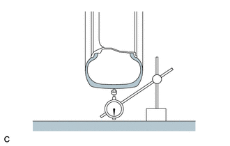
(b) Using a dial indicator, check the runout of the tires. Maximum Tire Runout: 1.4 mm (0.0551 in.) |
|
2. ROTATE TIRES
(a) Remove the wheel assembly.
Click here .gif)

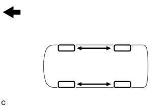
.png) |
Front |
(b) Rotate the tires as shown in the illustration.
(c) Install the wheel assembly.
Click here .gif)
(d) Perform initialization. (w/ Tire Pressure Warning System)
Click here .gif)
3. INSPECT AND ADJUST WHEEL BALANCE
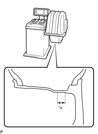
(a) Inspect and adjust the off-the-car balance.
(1) for Steel Wheel:
Maximum Wheel Imbalance:
8.0 g (0.0176 lb)
HINT:
- Use clip-on type balance weights for both the inner and outer side.
- If the tires vibrate even after the off-the-car balance adjustment, adjust the wheel balance with on-the-car balancing as necessary.
|
(2) for Alloy Wheel: Maximum Wheel Imbalance: 8.0 g (0.0176 lb) NOTICE:
HINT:
|
|
4. INSPECT FRONT AXLE HUB BEARING
Click here .gif)
5. INSPECT REAR AXLE HUB BEARING
- for 2WD:
Click here
.gif)
- for AWD:
Click here
.gif)


