Toyota Corolla Cross: Inspection
INSPECTION
PROCEDURE
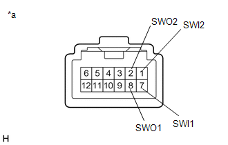
1. INSPECT ELECTRIC PARKING BRAKE SWITCH ASSEMBLY
(a) Check the resistance.
|
(1) Measure the resistance according to the value(s) in the
table below.
Standard Resistance:
|
Tester Connection
|
Condition
|
Specified Condition
|
|
7 (SWI1) - 8 (SWO1)
|
OFF (Release)
|
100 kΩ or higher
|
|
7 (SWI1) - 8 (SWO1)
|
ON (Lock)
|
10 Ω or less
|
|
7 (SWI1) - 8 (SWO1)
|
Switch not operated
|
100 kΩ or higher
|
|
7 (SWI1) - 1 (SWI2)
|
OFF (Release)
|
10 Ω or less
|
|
7 (SWI1) - 1 (SWI2)
|
ON (Lock)
|
10 Ω or less
|
|
7 (SWI1) - 1 (SWI2)
|
Switch not operated
|
100 kΩ or higher
|
|
7 (SWI1) - 2 (SWO2)
|
OFF (Release)
|
10 Ω or less
|
|
7 (SWI1) - 2 (SWO2)
|
ON (Lock)
|
100 kΩ or higher
|
|
7 (SWI1) - 2 (SWO2)
|
Switch not operated
|
10 Ω or less
|
|
1 (SWI2) - 8 (SWO1)
|
OFF (Release)
|
100 kΩ or higher
|
|
1 (SWI2) - 8 (SWO1)
|
ON (Lock)
|
10 Ω or less
|
|
1 (SWI2) - 8 (SWO1)
|
Switch not operated
|
10 Ω or less
|
|
1 (SWI2) - 2 (SWO2)
|
OFF (Release)
|
10 Ω or less
|
|
1 (SWI2) - 2 (SWO2)
|
ON (Lock)
|
100 kΩ or higher
|
|
1 (SWI2) - 2 (SWO2)
|
Switch not operated
|
100 kΩ or higher
|
|
 |
|
*a
|
Component without harness connected
(Electric Parking Brake Switch Assembly)
|
|
|
(2) If the result is not as specified, replace the electric parking
brake switch assembly.
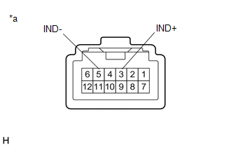
(b) Check the Illumination.
|
(1) Apply auxiliary battery voltage to the electric parking
brake switch assembly and check that the switch illuminates.
OK:
|
Tester Connection
|
Specified Condition
|
|
Auxiliary battery positive (+) → 3 (IND+)
Auxiliary battery negative (-) → 5 (IND-)
|
Illuminates
|
|
 |
|
*a
|
Component without harness connected
(Electric Parking Brake Switch Assembly)
|
|
|
(2) If the result is not as specified, replace the electric parking
brake switch assembly.
READ NEXT:
INSTALLATION
CAUTION / NOTICE / HINT
COMPONENTS (INSTALLATION)
Procedure
Part Name Code
1
COMBINATION SWITCH ASSEMBLY
PRECAUTION
TROUBLESHOOTING PRECAUTIONS
(a) When inspecting the rear brakes, disconnect the connector or
disconnect the cable from the negative (-) auxiliary battery terminal in order to
shut off
SEE MORE:
Removal
REMOVAL
CAUTION / NOTICE / HINT
COMPONENTS (REMOVAL)
Procedure
Part Name Code
1
CLEARANCE LIGHT SOCKET
-
-
-
-
2
CLEARANCE LIGHT BULB
INSPECTION PROCEDURE 1. INSPECT DOOR CONTROL TRANSMITTER SUB-ASSEMBLY
(a) Inspect operation of the door control transmitter sub-assembly. (1) Remove the transmitter battery from the door control transmitter sub-assembly.
Click here
(2) Install a new or non-depleted transmitter battery.


