Toyota Corolla Cross: Front Floor Electrical Key Oscillator Circuit Open (B27A513)
DESCRIPTION
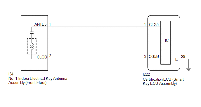
The certification ECU (smart key ECU assembly) generates a request signal and transmits the signal to the No. 1 indoor electrical key antenna assembly (front floor). For the No. 1 indoor electrical key antenna assembly (front floor) to detect when the electrical key transmitter sub-assembly is in the cabin, the signal from the certification ECU (smart key ECU assembly) requesting a response from the electrical key transmitter sub-assembly is transmitted inside the vehicle. DTC B27A513 is stored by the certification ECU (smart key ECU assembly) when an open is detected between the certification ECU (smart key ECU assembly) and No. 1 indoor electrical key antenna assembly (front floor) (between terminals CLG5 and ANTE5, or terminals CG5B and CLGB).
|
DTC No. | Detection Item |
DTC Detection Condition | Trouble Area |
Note |
|---|---|---|---|---|
| B27A513 |
Front Floor Electrical Key Oscillator Circuit Open |
An open is detected in the circuit between the certification ECU (smart key ECU assembly) and No. 1 indoor electrical key antenna assembly (front floor) (CLG5 - ANTE5, CG5B - CLGB) (1 trip detection logic*). |
| DTC Output Confirmation Operation:
|
- *: Only output while a malfunction is present.
|
Vehicle Condition when Malfunction Detected |
Fail-safe Operation when Malfunction Detected |
|---|---|
|
When electrical key transmitter sub-assembly is in front seat area:
| - |
|
DTC No. | Data List and Active Test |
|---|---|
|
B27A513 | Key diagnostic mode can be used to perform troubleshooting |
WIRING DIAGRAM
CAUTION / NOTICE / HINT
NOTICE:
- When using the GTS with the ignition switch off, connect the GTS to the DLC3 and turn a courtesy light switch on and off at intervals of 1.5 seconds or less until communication between the GTS and the vehicle begins. Then select the vehicle type under manual mode and enter the following menus: Body Electrical / Smart Key. While using the GTS, periodically turn a courtesy light switch on and off at intervals of 1.5 seconds or less to maintain communication between the GTS and the vehicle.
- The smart key system (for Start Function) uses the LIN communication system and CAN communication system. Inspect the communication function by following How to Proceed with Troubleshooting. Troubleshoot the smart key system (for Start Function) after confirming that the communication systems are functioning properly.
Click here
.gif)
- Before replacing the certification ECU (smart key ECU assembly), refer to Registration.
Click here
- After repair, confirm that no DTCs are output by performing "DTC Output Confirmation Operation".
PROCEDURE
|
1. | CHECK CONNECTOR CONNECTION |
(a) Check that the connectors are properly connected to the certification ECU (smart key ECU assembly) and No. 1 indoor electrical key antenna assembly (front floor).
OK:
Connectors are properly connected.
| NG | .gif) | CONNECT CONNECTORS PROPERLY |
|
.gif)
| 2. |
CHECK HARNESS AND CONNECTOR (CERTIFICATION ECU (SMART KEY ECU ASSEMBLY) - NO. 1 INDOOR ELECTRICAL KEY ANTENNA ASSEMBLY (FRONT FLOOR)) |
(a) Disconnect the I222 certification ECU (smart key ECU assembly) connector.
(b) Disconnect the I34 No. 1 indoor electrical key antenna assembly (front floor) connector.
(c) Measure the resistance according to the value(s) in the table below.
Standard Resistance:
|
Tester Connection | Condition |
Specified Condition |
|---|---|---|
|
I222-4 (CLG5) - I34-1 (ANTE5) |
Always | Below 1 Ω |
|
I222-5 (CG5B) - I34-2 (CLGB) |
Always | Below 1 Ω |
| NG | | REPAIR OR REPLACE HARNESS OR CONNECTOR |
|
| 3. |
CHECK CERTIFICATION ECU (SMART KEY ECU ASSEMBLY) |
(a) Connect the I222 certification ECU (smart key ECU assembly) connector.
|
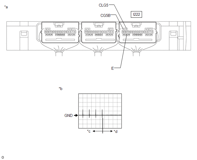
*a | Component with harness connected (Certification ECU (Smart Key ECU Assembly)) |
*b | Waveform |
|
*c | For 30 seconds after any door closed |
*d | After 30 seconds or more have elapsed since any door closed |
(b) Using an oscilloscope, check the waveform.
OK:
|
Tester Connection | Condition |
Tool Setting | Specified Condition |
|---|---|---|---|
|
I222-4 (CLG5) - I222-29 (E) | Procedure:
| 2 V/DIV., 500 ms./DIV. |
Pulse generation (See waveform) |
|
I222-5 (CG5B) - I222-29 (E) | Procedure:
| 2 V/DIV., 500 ms./DIV. |
Pulse generation (See waveform) |
| OK | | REPLACE NO. 1 INDOOR ELECTRICAL KEY ANTENNA ASSEMBLY (FRONT FLOOR) |
| NG | | REPLACE CERTIFICATION ECU (SMART KEY ECU ASSEMBLY) |


