Toyota Corolla Cross: Engine/Power Switch Signal Compare Failure (B227862)
DESCRIPTION
This DTC is stored when the SSW1 contact signal, SSW2 contact signal and SSW3 contact signal, which are detected when the power switch is operated, do not match.
|
DTC No. | Detection Item |
DTC Detection Condition | Trouble Area |
Note |
|---|---|---|---|---|
| B227862 |
Engine/Power Switch Signal Compare Failure |
When the power switch is operated, the SSW1 contact signal, SSW2 contact signal and SSW3 contact signal do not match. |
| DTC Output Confirmation Operation:
|
|
Vehicle Condition when Malfunction Detected |
Fail-safe Function when Malfunction Detected |
|---|---|
|
If there is a malfunction in only one of the terminals SS1, SS2 or SS3, the system can still operate normally. |
When only one terminal malfunctions, that terminal is disabled and the system operates normally. |
|
DTC No. | Data List and Active Test |
|---|---|
|
B227862 | Power Source Control
|
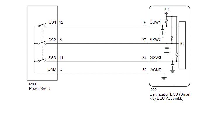
WIRING DIAGRAM
CAUTION / NOTICE / HINT
NOTICE:
- When using the GTS with the ignition switch off, connect the GTS to the DLC3 and turn a courtesy light switch on and off at intervals of 1.5 seconds or less until communication between the GTS and the vehicle begins.
Then select Model Code "KEY REGIST" under manual mode and enter the following menus: Body Electrical / Start Key(CAN). While using the GTS, periodically turn a courtesy light switch on and off at intervals of 1.5 seconds or less to maintain communication between the GTS and the vehicle.
- The smart key system (for Start Function) uses the LIN communication system and CAN communication system. Inspect the communication function by following How to Proceed with Troubleshooting. Troubleshoot the smart key system (for Start Function) after confirming that the communication systems are functioning properly.
Click here
.gif)
- Before replacing the certification ECU (smart key ECU assembly), refer to Registration.
Click here
- After repair, confirm that no DTCs are output by performing "DTC Output Confirmation Operation".
PROCEDURE
|
1. | READ VALUE USING GTS (PUSH START SWITCH 1, PUSH START SWITCH 2, PUSH START SWITCH 3) |
(a) Read the Data List according to the display on the GTS.
Body Electrical > Power Source Control > Data List|
Tester Display | Measurement Item |
Range | Normal Condition |
Diagnostic Note |
|---|---|---|---|---|
|
Push Start Switch 1 | Power switch 1 status |
OFF or ON | OFF: Power switch not pressed ON: Power switch pressed |
|
| Push Start Switch 2 |
Power switch 2 status |
OFF or ON | OFF: Power switch not pressed ON: Power switch pressed |
|
| Push Start Switch 3 |
Power switch 3 status |
OFF or ON | OFF: Power switch not pressed ON: Power switch pressed |
|
|
Tester Display |
|---|
| Push Start Switch 1 |
|
Push Start Switch 2 |
|
Push Start Switch 3 |
OK:
The GTS display changes correctly in response to the power switch operation.
| NG | .gif) | GO TO STEP 3 |
|
.gif)
| 2. |
READ VALUE USING GTS (PUSH START SWITCH 1, PUSH START SWITCH 2, PUSH START SWITCH 3) |
(a) According to the display on the GTS, read the Data List while wiggling the wire harness.
Body Electrical > Power Source Control > Data List|
Tester Display | Measurement Item |
Range | Normal Condition |
Diagnostic Note |
|---|---|---|---|---|
|
Push Start Switch 1 | Power switch 1 status |
OFF or ON | OFF: Power switch not pressed ON: Power switch pressed |
|
| Push Start Switch 2 |
Power switch 2 status |
OFF or ON | OFF: Power switch not pressed ON: Power switch pressed |
|
| Push Start Switch 3 |
Power switch 3 status |
OFF or ON | OFF: Power switch not pressed ON: Power switch pressed |
|
|
Tester Display |
|---|
| Push Start Switch 1 |
|
Push Start Switch 2 |
|
Push Start Switch 3 |
OK:
The GTS display changes correctly in response to the power switch operation.
| OK | | USE SIMULATION METHOD TO CHECK |
| NG | | REPAIR OR REPLACE HARNESS OR CONNECTOR |
| 3. |
CHECK HARNESS AND CONNECTOR (CERTIFICATION ECU (SMART KEY ECU ASSEMBLY) - POWER SWITCH) |
(a) Disconnect the I222 certification ECU (smart key ECU assembly) connector.
(b) Disconnect the I280 power switch connector.
(c) Measure the resistance according to the value(s) in the table below.
Standard Resistance:
|
Tester Connection | Condition |
Specified Condition |
|---|---|---|
|
I222-19 (SSW1) - I280-12 (SS1) |
Always | Below 1 Ω |
|
I222-27 (SSW2) - I280-6 (SS2) |
Always | Below 1 Ω |
|
I222-23 (SSW3) - I280-11 (SS3) |
Always | Below 1 Ω |
|
I222-30 (AGND) - I280-3 (GND) |
Always | Below 1 Ω |
|
I222-19 (SSW1) or I280-12 (SS1) - Other terminals and body ground |
Always | 10 kΩ or higher |
|
I222-27 (SSW2) or I280-6 (SS2) - Other terminals and body ground |
Always | 10 kΩ or higher |
|
I222-23 (SSW3) or I280-11 (SS3) - Other terminals and body ground |
Always | 10 kΩ or higher |
|
I222-30 (AGND) or I280-3 (GND) - Other terminals and body ground |
Always | 10 kΩ or higher |
| NG | | REPAIR OR REPLACE HARNESS OR CONNECTOR |
|
| 4. |
INSPECT POWER SWITCH |
Click here
| OK | |
REPLACE CERTIFICATION ECU (SMART KEY ECU ASSEMBLY) |
| NG | | REPLACE POWER SWITCH |


