Toyota Corolla Cross: Engine Immobiliser System Signal (Some Circuit Quantity, Reported via Serial Data) Invalid (B279986)
DESCRIPTION
If there is a communication malfunction between the hybrid vehicle control ECU and ID code box (immobiliser code ECU), or when the communication ID codes do not match, the hybrid vehicle control ECU stores this DTC.
|
DTC No. | Detection Item |
DTC Detection Condition | Trouble Area |
Note |
|---|---|---|---|---|
| B279986 |
Engine Immobiliser System Signal (Some Circuit Quantity, Reported via Serial Data) Invalid |
Either of the following conditions is met (1 trip detection logic*):
|
| DTC output confirmation operation (Perform either of the following):
|
- *: Only output while a malfunction is present.
|
Vehicle Condition when Malfunction Detected |
Fail-safe Operation when Malfunction Detected |
|---|---|
|
Hybrid control system cannot be started |
- |
|
DTC No. | Data List and Active Test |
|---|---|
|
B279986 | - |
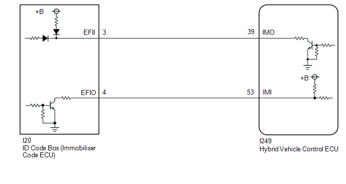
WIRING DIAGRAM
CAUTION / NOTICE / HINT
NOTICE:
- When using the GTS with the ignition switch off, connect the GTS to the DLC3 and turn a courtesy light switch on and off at intervals of 1.5 seconds or less until communication between the GTS and the vehicle begins.
Then select Model Code "KEY REGIST" under manual mode and enter the following menus: Body Electrical / Start Key(CAN). While using the GTS, periodically turn a courtesy light switch on and off at intervals of 1.5 seconds or less to maintain communication between the GTS and the vehicle.
- The smart key system (for Start Function) uses the LIN communication system and CAN communication system. Inspect the communication function by following How to Proceed with Troubleshooting. Troubleshoot the smart key system (for Start Function) after confirming that the communication systems are functioning properly.
Click here
.gif)
- Before replacing the hybrid vehicle control ECU or ID code box (immobiliser code ECU), refer to Registration.
Click here
- After performing repairs, confirm that no DTCs are output by performing "DTC Output Confirmation Operation".
- When the hybrid vehicle control ECU is replaced, update the ECU security key.
Click here
HINT:
When DTC B279986 and the certification ECU (smart key ECU assembly) DTC are output simultaneously, first perform troubleshooting for the certification ECU (smart key ECU assembly) DTC.
PROCEDURE
| 1. |
REGISTER ECU COMMUNICATION ID |
(a) Register the ECU communication ID code.
Click here
|
.gif)
| 2. |
CHECK HYBRID VEHICLE CONTROL ECU (TERMINAL IMO) |
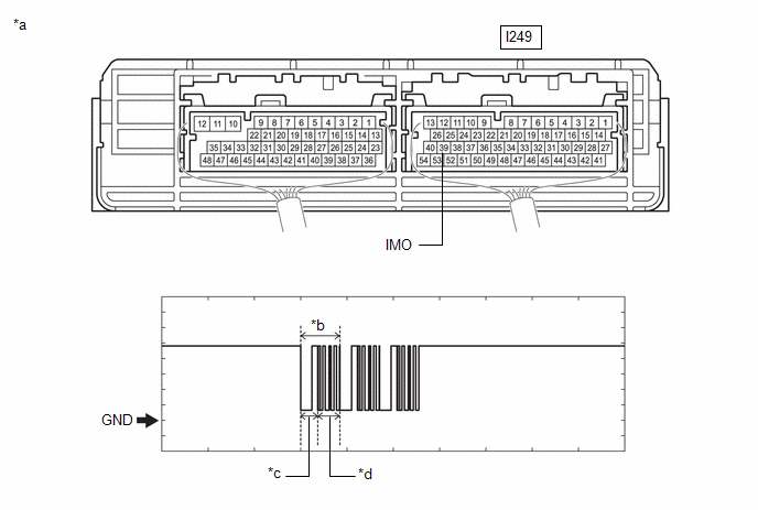
(a) Using an oscilloscope, check the waveform.
|
*a | Component with harness connected (Hybrid Vehicle Control ECU) |
*b | Waveform |
|
*c | Approximately 160 ms. |
*d | Approximately 270 ms. |
OK:
|
Tester Connection | Condition |
Tool Setting | Specified Condition |
|---|---|---|---|
|
I249-39 (IMO) - Body ground |
Within 3 seconds of hybrid control system start or within 3 seconds of ignition switch turned to ON after cable disconnected and reconnected to auxiliary battery |
2 V/DIV., 500 ms./DIV. |
Pulse generation (See waveform) |
|
Result | Proceed to |
|---|---|
|
Normal waveform | A |
|
Terminal IMO stuck low (2.4 V or less) |
B |
| Waveform not output, has abnormal wavelength or shape or Terminal IMO stuck high (12V) |
C |
| B |
.gif) | GO TO STEP 6 |
| C |
| GO TO STEP 8 |
|
| 3. |
CHECK HYBRID VEHICLE CONTROL ECU (TERMINAL IMI) |
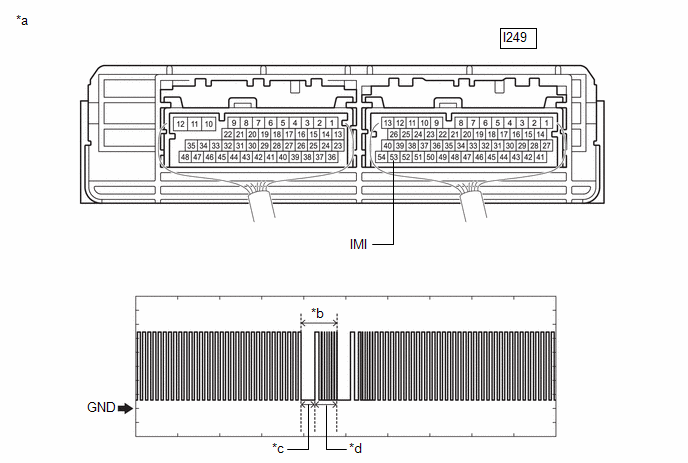
(a) Using an oscilloscope, check the waveform.
|
*a | Component with harness connected (Hybrid Vehicle Control ECU) |
*b | Waveform |
|
*c | Approximately 160 ms. |
*d | Approximately 270 ms. |
OK:
|
Tester Connection | Condition |
Tool Setting | Specified Condition |
|---|---|---|---|
|
I249-53 (IMI) - Body ground |
Within 3 seconds of hybrid control system start or within 3 seconds of ignition switch turned to ON after cable disconnected and reconnected to auxiliary battery |
2 V/DIV., 500 ms./DIV. |
Pulse generation (See waveform) |
| NG | | REPLACE ID CODE BOX (IMMOBILISER CODE ECU) |
|
| 4. |
REGISTER ECU COMMUNICATION ID |
(a) Register the ECU communication ID code.
Click here
|
| 5. |
CHECK WHETHER HYBRID CONTROL SYSTEM STARTS |
(a) Using an electrical key transmitter sub-assembly which is registered to the vehicle, turn the ignition switch to ON.
(b) Check that the hybrid control system starts 5 seconds after the ignition switch turned to ON.
OK:
Hybrid control system starts normally.
| OK | | END (ECU COMMUNICATION ID HAS NOT BEEN REGISTERED) |
| NG | | REPLACE HYBRID VEHICLE CONTROL ECU |
| 6. |
CHECK HYBRID VEHICLE CONTROL ECU |
(a) Disconnect the I249 hybrid vehicle control ECU connector.
(b) Measure the voltage according to the value(s) in the table below.
Standard Voltage:
|
Tester Connection | Condition |
Specified Condition |
|---|---|---|
|
I249-39 (IMO) - Body ground |
Ignition switch turned to ON using registered electrical key transmitter sub-assembly |
Terminal IMO stuck low (2.4 V or less) |
|
Terminal IMO stuck high (12 V) or abnormal waveform |
|
Result | Proceed to |
|---|---|
|
Terminal IMO stuck low (2.4 V or less) |
A |
| Terminal IMO stuck high (12 V) or abnormal waveform |
B |
| B |
| REPLACE HYBRID VEHICLE CONTROL ECU |
|
| 7. |
CHECK HARNESS AND CONNECTOR (ID CODE BOX (IMMOBILISER CODE ECU) - HYBRID VEHICLE CONTROL ECU) |
(a) Disconnect the I20 ID code box (immobiliser code ECU) connector.
(b) Measure the resistance according to the value(s) in the table below.
Standard Resistance:
|
Tester Connection | Condition |
Specified Condition |
|---|---|---|
|
I20-3 (EFII) - I249-39 (IMO) |
Always | Below 1 Ω |
|
I20-3 (EFII) or I249-39 (IMO) - Other terminals and body ground |
Always | 10 kΩ or higher |
|
I20-4 (EFIO) - I249-53 (IMI) |
Always | Below 1 Ω |
|
I20-4 (EFIO) or I249-53 (IMI) - Other terminals and body ground |
Always | 10 kΩ or higher |
| OK | | REPLACE ID CODE BOX (IMMOBILISER CODE ECU) |
| NG | | REPAIR OR REPLACE HARNESS OR CONNECTOR |
| 8. |
CHECK HARNESS AND CONNECTOR (ID CODE BOX (IMMOBILISER CODE ECU) - HYBRID VEHICLE CONTROL ECU) |
(a) Disconnect the I20 ID code box (immobiliser code ECU) connector.
(b) Disconnect the I249 hybrid vehicle control ECU connector.
(c) Measure the resistance according to the value(s) in the table below.
Standard Resistance:
|
Tester Connection | Condition |
Specified Condition |
|---|---|---|
|
I20-3 (EFII) - I249-39 (IMO) |
Always | Below 1 Ω |
|
I20-3 (EFII) or I249-39 (IMO) - Other terminals and body ground |
Always | 10 kΩ or higher |
| OK | | REPLACE HYBRID VEHICLE CONTROL ECU |
| NG | | REPAIR OR REPLACE HARNESS OR CONNECTOR |
READ NEXT:
 Engine Immobiliser System Circuit Short to Battery (B279A12)
DESCRIPTION If the communication line (IMI - EFIO) between the hybrid vehicle control ECU and ID code box (immobiliser code ECU) is stuck high, the hybrid vehicle control ECU will store this DTC.
Engine Immobiliser System Incorrect Assembly (B279C95)
DESCRIPTION If a hybrid vehicle control ECU that is incompatible with the immobiliser function is installed, the hybrid vehicle control ECU will store this DTC.
DTC No. Detection Item
DTC
Front Floor Electrical Key Oscillator Circuit Open (B27A513)
DESCRIPTION The certification ECU (smart key ECU assembly) generates a request signal and transmits the signal to the No. 1 indoor electrical key antenna assembly (front floor). For the No. 1 indoor e
SEE MORE:
 Right Electric Parking Brake Actuator Control (C061000,C061011)
DESCRIPTION
DTC No.
Detection Item
DTC Detection Condition
Trouble Area
Memory
Note
C061000
Right Electric Parking Brake Actuator Control
Diagnosis Condition:
-
Malfunction Status:
Combination Switch
InspectionINSPECTION PROCEDURE
1. INSPECT EV DRIVE MODE SWITCH (COMBINATION SWITCH ASSEMBLY) (a) Check the resistance.
(1) Measure the resistance according to the value(s) in the table below.
Standard Resistance:
Tester Connection
Condition Specified Condition
