Toyota Corolla Cross: Engine Failed to Start Mechanical Linkage Failure (P1C7779)
DTC SUMMARY
MALFUNCTION DESCRIPTION
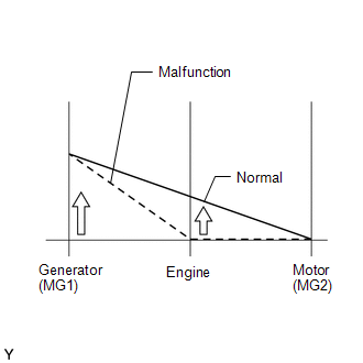
This DTC is stored when the hybrid vehicle control ECU determines that the hybrid vehicle transaxle assembly has seized or that there is a hybrid vehicle transaxle assembly malfunction in the drivetrain. The cause of this malfunction may be one of the following:
Engine malfunction- Seizure due to insufficient engine oil
- Seizure due to insufficient coolant
- Damaged engine
- Seizure due to insufficient ATF
- Damaged hybrid vehicle transaxle internal components
- Damaged transmission input damper assembly
DESCRIPTION
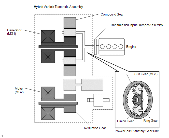
The hybrid vehicle transaxle assembly consists of the planetary gear unit, generator (MG1) and motor (MG2). The planetary gear unit uses a planetary gear to split the engine output into mechanical power and electrical power in accordance with driving requests when the vehicle is being driven or the HV battery is being charged. When accelerating, motor (MG2) assists engine output by increasing vehicle driving force. Motor (MG2) also converts braking energy, which would otherwise be consumed in the form of heat during braking, into electrical energy. This recovered energy is stored in the HV battery. Generator (MG1) supplies power, which is used for charging the HV battery or driving motor (MG2), and also regulates the amount of electricity being generated. In addition, generator (MG1) is used as a starter motor to start the engine.
If the hybrid vehicle control ECU detects that the engine or transaxle gear has seized, the hybrid vehicle control ECU will perform fail-safe control. Also, if a substance or object is preventing the engine or transaxle internal components from rotating, the hybrid vehicle control ECU will perform fail-safe control.

|
DTC No. | Detection Item |
DTC Detection Condition |
Trouble Area | MIL |
Warning Indicate | Note |
|---|---|---|---|---|---|---|
|
P1C7779 | Engine Failed to Start Mechanical Linkage Failure |
The engine does not start even though it is being cranked (transaxle input circuit malfunction (engine system)) (1 trip detection logic) |
| Does not come on |
Master Warning: Comes on |
SAE Code: P0A0F |
CONFIRMATION DRIVING PATTERN
HINT:
After repair has been completed, clear the DTCs and then check that the vehicle has returned to normal by performing the following All Readiness check procedure.
Click here .gif)
- Connect the GTS to the DLC3.
- Turn the ignition switch to ON and turn the GTS on.
- Clear the DTCs (even if no DTCs are stored, perform the clear DTC procedure).
- Turn the ignition switch off and wait for 2 minutes or more.
- Turn the ignition switch to ON and turn the GTS on.
- Turn the ignition switch to ON (READY).
- While driving the vehicle at a speed of 20 km/h (12 mph) or more in EV mode, depress the accelerator pedal to start the engine, and drive the vehicle for 3 seconds or more.*1
*1: When the HV system is normal, the engine starts when the accelerator pedal is depressed halfway or more. If the HV system is malfunctioning, the engine may not start. Even in this case, drive the vehicle at a speed of 20 km/h (12 mph) or more in EV mode for 3 seconds or more.
- Enter the following menus: Powertrain / Hybrid Control / Utility / All Readiness.
- Check the DTC judgment result.
HINT:
- If the judgment result shows NORMAL, the system is normal.
- If the judgment result shows ABNORMAL, the system has a malfunction.
- If the judgment result shows INCOMPLETE, perform driving pattern again.
CAUTION / NOTICE / HINT
HINT:
- Engine lock or a mechanical malfunction has occurred inside the hybrid vehicle transaxle assembly.
- If this DTC is output, the engine or gears in the transaxle may have seized. Before performing this inspection, check the engine oil, hybrid transaxle fluid, coolant (for Engine) and coolant (for Inverter) levels.
PROCEDURE
|
1. | CHECK CRANKSHAFT PULLEY REVOLUTION (P POSITION) |
(a) Make sure that the shift lever is in P position.
(b) Lift up the vehicle.
(c) Turn the crankshaft pulley using hand tools to check if the crankshaft can rotate smoothly.
CAUTION:
Do not turn the ignition switch to ON (READY) while performing this inspection. Be sure to turn the ignition switch off before performing this inspection, to prevent the engine from starting.
NOTICE:
Engine compression causes resistance when turning the crankshaft pulley. Check if the crankshaft rotates smoothly (or if it is locked) by manually applying sufficient torque to turn the crankshaft pulley. The torque required to turn the crankshaft pulley should be the same as for a known good vehicle of the same type.
OK:
The crankshaft rotates smoothly.
(d) Lower the vehicle.
| NG | .gif) | GO TO STEP 6 |
|
|
2. | CLEAR DTC |
(a) Clear the DTCs.
Powertrain > Hybrid Control > Clear DTCs Powertrain > Engine > Clear DTCs(b) Turn the ignition switch off.
|
|
3. | CHECK ENGINE RACING |
(a) Turn the ignition switch to ON (READY).
(b) Read the Data List.
Powertrain > Hybrid Control > Data List|
Tester Display |
|---|
|
Engine Speed |
|
Generator Revolution |
| (1) While the READY indicator is on, depress the accelerator pedal for 10 seconds. OK: "Generator Revolution" is approximately 3.6 times "Engine Speed". HINT:
|
|
(c) Turn the ignition switch off.
| NG | .gif) | REPLACE HYBRID VEHICLE TRANSAXLE ASSEMBLY |
|
|
4. | CHECK CREEP MOVEMENT |
(a) Turn the ignition switch to ON (READY).
(b) Depress the brake pedal, move the shift lever to D, and release the brake pedal.
OK:
The wheels turn (the vehicle creeps forward).
(c) Turn the ignition switch off.
| NG | .gif) | REPLACE HYBRID VEHICLE TRANSAXLE ASSEMBLY |
|
|
5. | INSPECT ENGINE SPEED |
(a) Turn the ignition switch to ON (READY).
(b) Read the Data List.
Powertrain > Hybrid Control > Data List|
Tester Display |
|---|
|
Engine Speed |
|
Generator Revolution |
|
Motor Revolution |
(1) Move the shift lever to D.
(2) Fully depress the accelerator pedal when the vehicle speed is 10 km/h (6 mph) or more.
NOTICE:
Perform this test only in an appropriate safe location, in accordance with all local laws.
(3) Calculate the difference between the value of "Engine Speed" and "(0.28 x Generator Revolution) + (0.19 x Motor Revolution)".
|
Result | Proceed to |
|---|---|
|
The absolute value of the difference is less than 500 rpm. |
A |
| The absolute value of the difference is 500 rpm or more continuously for 1 second. |
B |
(c) Turn the ignition switch off.
| A | .gif) | REPLACE HYBRID VEHICLE TRANSAXLE ASSEMBLY |
| B | .gif) | REPLACE TRANSMISSION INPUT DAMPER ASSEMBLY |
|
6. | CHECK CRANKSHAFT PULLEY REVOLUTION (N POSITION) |
(a) Lift up the vehicle.
(b) Move the shift lever to N.
(c) Turn the crankshaft pulley using hand tools to check if the crankshaft can rotate smoothly.
CAUTION:
Do not turn the ignition switch to ON (READY) while performing this inspection. Be sure to turn the ignition switch off before performing this inspection, to prevent the engine from starting.
NOTICE:
Engine compression causes resistance when turning the crankshaft pulley. Check if the crankshaft rotates smoothly (or if it is locked) by manually applying sufficient torque to turn the crankshaft pulley. The torque required to turn the crankshaft pulley should be the same as for a known good vehicle of the same type.
OK:
The crankshaft rotates smoothly.
(d) Move the shift lever to P.
(e) Lower the vehicle.
| OK | .gif) |
REPLACE HYBRID VEHICLE TRANSAXLE ASSEMBLY |
| NG | .gif) | REPAIR OR REPLACE ENGINE |

.gif)


