Toyota Corolla Cross: Driver Side Power Window does not Operate with Power Window Master Switch
DESCRIPTION
When the ignition switch is ON, the power window regulator motor assembly (for driver door) is operated by the multiplex network master switch assembly. The power window regulator motor assembly (for driver door) has motor, regulator and ECU functions.
WIRING DIAGRAM
Click here .gif)
CAUTION / NOTICE / HINT
NOTICE:
- Inspect the fuses for circuits related to this system before performing the following procedure.
- If the power window regulator motor assembly (for driver door) has been replaced with a new one, initialize the power window control system.
Click here
- The power window control system uses the LIN communication system. Inspect the communication function by following How to Proceed with Troubleshooting. Troubleshoot the power window control system after confirming that the communication system is functioning properly.
Click here
- Before replacing the main body ECU (multiplex network body ECU), refer to Registration.*1
- for HEV Model:
Click here
- for Gasoline Model:
Click here
- *1: w/ Smart Key System
- for HEV Model:
PROCEDURE
|
1. | READ VALUE USING GTS |
(a) Read the Data List according to the display on the GTS.
Body Electrical > Main Body > Data List|
Tester Display | Measurement Item |
Range | Normal Condition |
Diagnostic Note |
|---|---|---|---|---|
|
Communication D-Door Motor |
Connection status between power window regulator motor assembly (for driver door) and main body ECU (multiplex network body ECU) |
STOP or OK | STOP: Communication stopped OK: Normal communication |
- |
| Communication Master Switch |
Connection status between multiplex network master switch assembly and main body ECU (multiplex network body ECU) |
STOP or OK | STOP: Communication stopped OK: Normal communication |
- |
|
Tester Display |
|---|
| Communication D-Door Motor |
|
Communication Master Switch |
OK:
OK is displayed for each Data List item above.
| NG | .gif) | GO TO LIN COMMUNICATION SYSTEM |
|
.gif)
| 2. |
READ VALUE USING GTS |
(a) Read the Data List according to the display on the GTS.
Body Electrical > Main Body > Data List|
Tester Display | Measurement Item |
Normal Condition | Reference Value |
Diagnostic Note |
|---|---|---|---|---|
|
D Door Power Window UP Switch |
Driver door power window manual up switch |
OFF or ON | OFF: Manual up switch not being operated ON: Manual up switch being operated |
- |
| D Door Power Window DOWN Switch |
Driver door power window manual down switch |
OFF or ON | OFF: Manual down switch not being operated ON: Manual down switch being operated |
- |
|
Tester Display |
|---|
| D Door Power Window UP Switch |
|
D Door Power Window DOWN Switch |
OK:
On the GTS screen, ON or OFF is displayed accordingly.
| NG | | GO TO STEP 4 |
|
| 3. |
PERFORM ACTIVE TEST USING GTS |
(a) Perform the Active Test according to the display on the GTS.
Body Electrical > Main Body > Active Test|
Tester Display | Measurement Item |
Control Range | Diagnostic Note |
|---|---|---|---|
|
D Door Power Window UP |
Driver door power window up activate |
OFF/ON | - |
|
D Door Power Window DOWN |
Driver door power window down activate |
OFF/ON | - |
|
Tester Display |
|---|
| D Door Power Window UP |
|
Tester Display |
|---|
| D Door Power Window DOWN |
HINT:
Up and down movement does not occur if the arrow is not pressed and held.
OK:
Driver door power window operates normally.
| OK | | REPLACE MAIN BODY ECU (MULTIPLEX NETWORK BODY ECU) |
| NG | | REPLACE POWER WINDOW REGULATOR MOTOR ASSEMBLY (for Driver Door) |
| 4. |
CHECK MULTIPLEX NETWORK MASTER SWITCH ASSEMBLY |
| (a) Disconnect the power window regulator motor assembly (for driver door) connector. |
|
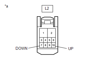
(b) Measure the voltage according to the value(s) in the table below.
Standard Voltage:
|
Tester Connection | Switch Condition |
Specified Condition |
|---|---|---|
|
L2-10 (UP) - Body ground |
Ignition switch ON | 11 to 14 V |
|
L2-7 (DOWN) - Body ground |
Ignition switch ON | 11 to 14 V |
| NG | | GO TO STEP 6 |
|
| 5. |
INSPECT POWER WINDOW REGULATOR MOTOR ASSEMBLY (for Driver Door) |
Click here
| OK | | REPLACE MAIN BODY ECU (MULTIPLEX NETWORK BODY ECU) |
| NG | | REPLACE POWER WINDOW REGULATOR MOTOR ASSEMBLY (for Driver Door) |
| 6. |
CHECK HARNESS AND CONNECTOR (MULTIPLEX NETWORK MASTER SWITCH ASSEMBLY - POWER WINDOW REGULATOR MOTOR ASSEMBLY (for Driver Door)) |
(a) Disconnect the L7 multiplex network master switch assembly connector.
(b) Disconnect the L2 power window regulator motor assembly (for driver door) connector.
(c) Measure the resistance according to the value(s) in the table below.
Standard Resistance:
|
Tester Connection | Condition |
Specified Condition |
|---|---|---|
|
L7-20 (UP) - L2-10 (UP) |
Always | Below 1 Ω |
|
L7-15 (DOWN) - L2-7 (DOWN) |
Always | Below 1 Ω |
|
L7-20 (UP) or L2-10 (UP) - Body ground |
Always | 10 kΩ or higher |
|
L7-15 (DOWN) or L2-7 (DOWN) - Body ground |
Always | 10 kΩ or higher |
| OK | | REPLACE MULTIPLEX NETWORK MASTER SWITCH ASSEMBLY |
| NG | | REPAIR OR REPLACE HARNESS OR CONNECTOR |


