Toyota Corolla Cross: Door Unlock Detection Switch Circuit
DESCRIPTION
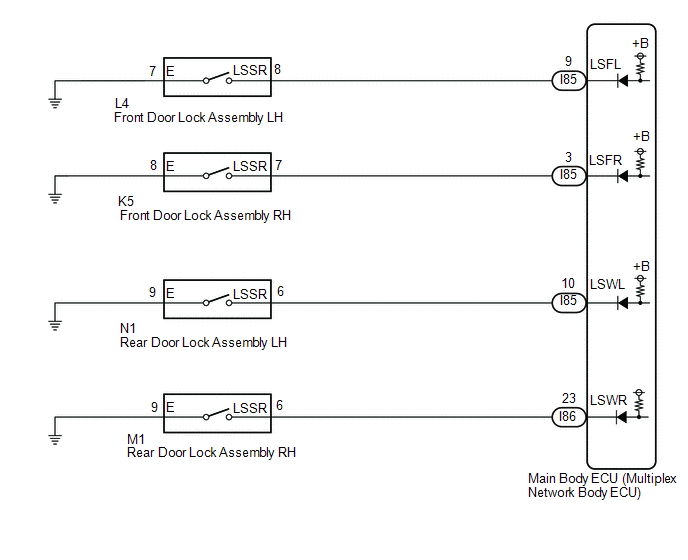
The main body ECU (multiplex network body ECU) detects the condition of each door unlock detection switch.
WIRING DIAGRAM
CAUTION / NOTICE / HINT
NOTICE:
Before replacing the main body ECU (multiplex network body ECU), refer to Registration.*1
for HEV Model: Click here .gif)
for Gasoline Model: Click here
- *1: w/ Smart Key System
PROCEDURE
|
1. | READ VALUE USING GTS |
(a) Read the Data List according to the display on the GTS.
Body Electrical > Main Body > Data List|
Tester Display | Measurement Item |
Range | Normal Condition |
Diagnostic Note |
|---|---|---|---|---|
|
FR Door Lock Position Switch Status |
Front door RH unlock detection switch signal |
LOCK or UNLOCK | LOCK: Front door RH locked UNLOCK: Front door RH unlocked |
- |
| FL Door Lock Position Switch Status |
Front door LH unlock detection switch signal |
LOCK or UNLOCK | LOCK: Front door LH locked UNLOCK: Front door LH unlocked |
- |
| RR Door Lock Position Switch Status |
Rear door RH unlock detection switch signal |
LOCK or UNLOCK | LOCK: Rear door RH locked UNLOCK: Rear door RH unlocked |
- |
| RL Door Lock Position Switch Status |
Rear door LH unlock detection switch signal |
LOCK or UNLOCK | LOCK: Rear door LH locked UNLOCK: Rear door LH unlocked |
- |
|
Tester Display |
|---|
| FR Door Lock Position Switch Status |
|
FL Door Lock Position Switch Status |
|
RR Door Lock Position Switch Status |
|
RL Door Lock Position Switch Status |
OK:
Normal conditions listed above are displayed.
|
Result | Proceed to |
|---|---|
|
OK | A |
|
NG ("FR Door Lock Position Switch Status" is not normal) |
B |
| NG ("FL Door Lock Position Switch Status" is not normal) |
C |
| NG ("RR Door Lock Position Switch Status" is not normal) |
D |
| NG ("RL Door Lock Position Switch Status" is not normal) |
E |
| A |
.gif) | PROCEED TO NEXT SUSPECTED AREA SHOWN IN PROBLEM SYMPTOMS TABLE |
| C |
| GO TO STEP 4 |
| D |
| GO TO STEP 6 |
| E |
| GO TO STEP 8 |
|
.gif)
| 2. |
INSPECT FRONT DOOR LOCK ASSEMBLY RH |
Click here
| NG | |
REPLACE FRONT DOOR LOCK ASSEMBLY RH |
|
| 3. |
CHECK HARNESS AND CONNECTOR (FRONT DOOR LOCK ASSEMBLY RH - MAIN BODY ECU (MULTIPLEX NETWORK BODY ECU) AND BODY GROUND) |
(a) Disconnect the I85 main body ECU (multiplex network body ECU) connector.
(b) Measure the resistance according to the value(s) in the table below.
Standard Resistance:
|
Tester Connection | Condition |
Specified Condition |
|---|---|---|
|
K5-7 (LSSR) - I85-3 (LSFR) |
Always | Below 1 Ω |
|
K5-8 (E) - Body ground |
Always | Below 1 Ω |
|
K5-7 (LSSR) - Body ground |
Always | 10 kΩ or higher |
|
I85-3 (LSFR) - Body ground |
Always | 10 kΩ or higher |
| OK | | REPLACE MAIN BODY ECU (MULTIPLEX NETWORK BODY ECU) |
| NG | | REPAIR OR REPLACE HARNESS OR CONNECTOR |
| 4. |
INSPECT FRONT DOOR LOCK ASSEMBLY LH |
Click here
| NG | |
REPLACE FRONT DOOR LOCK ASSEMBLY LH |
|
| 5. |
CHECK HARNESS AND CONNECTOR (FRONT DOOR LOCK ASSEMBLY LH - MAIN BODY ECU (MULTIPLEX NETWORK BODY ECU) AND BODY GROUND) |
(a) Disconnect the I85 main body ECU (multiplex network body ECU) connector.
(b) Measure the resistance according to the value(s) in the table below.
Standard Resistance:
|
Tester Connection | Condition |
Specified Condition |
|---|---|---|
|
L4-8 (LSSR) - I85-9 (LSFL) |
Always | Below 1 Ω |
|
L4-7 (E) - Body ground |
Always | Below 1 Ω |
|
L4-8 (LSSR) - Body ground |
Always | 10 kΩ or higher |
|
I85-9 (LSFL) - Body ground |
Always | 10 kΩ or higher |
| OK | | REPLACE MAIN BODY ECU (MULTIPLEX NETWORK BODY ECU) |
| NG | | REPAIR OR REPLACE HARNESS OR CONNECTOR |
| 6. |
INSPECT REAR DOOR LOCK ASSEMBLY RH |
Click here
| NG | |
REPLACE REAR DOOR LOCK ASSEMBLY RH |
|
| 7. |
CHECK HARNESS AND CONNECTOR (REAR DOOR LOCK ASSEMBLY RH - MAIN BODY ECU (MULTIPLEX NETWORK BODY ECU) AND BODY GROUND) |
(a) Disconnect the I86 main body ECU (multiplex network body ECU) connector.
(b) Measure the resistance according to the value(s) in the table below.
Standard Resistance:
|
Tester Connection | Condition |
Specified Condition |
|---|---|---|
|
M1-6 (LSSR) - I86-23 (LSWR) |
Always | Below 1 Ω |
|
M1-9 (E) - Body ground |
Always | Below 1 Ω |
|
M1-6 (LSSR) - Body ground |
Always | 10 kΩ or higher |
|
I86-23 (LSWR) - Body ground |
Always | 10 kΩ or higher |
| OK | | REPLACE MAIN BODY ECU (MULTIPLEX NETWORK BODY ECU) |
| NG | | REPAIR OR REPLACE HARNESS OR CONNECTOR |
| 8. |
INSPECT REAR DOOR LOCK ASSEMBLY LH |
Click here
| NG | |
REPLACE REAR DOOR LOCK ASSEMBLY RH |
|
| 9. |
CHECK HARNESS AND CONNECTOR (REAR DOOR LOCK ASSEMBLY LH - MAIN BODY ECU (MULTIPLEX NETWORK BODY ECU) AND BODY GROUND) |
(a) Disconnect the I85 main body ECU (multiplex network body ECU) connector.
(b) Measure the resistance according to the value(s) in the table below.
Standard Resistance:
|
Tester Connection | Condition |
Specified Condition |
|---|---|---|
|
N1-6 (LSSR) - I85-10 (LSWL) |
Always | Below 1 Ω |
|
N1-9 (E) - Body ground |
Always | Below 1 Ω |
|
N1-6 (LSSR) - Body ground |
Always | 10 kΩ or higher |
|
I85-10 (LSWL) - Body ground |
Always | 10 kΩ or higher |
| OK | | REPLACE MAIN BODY ECU (MULTIPLEX NETWORK BODY ECU) |
| NG | | REPAIR OR REPLACE HARNESS OR CONNECTOR |


