Toyota Corolla Cross: Disposal
DISPOSAL
CAUTION / NOTICE / HINT
CAUTION:
Before performing pre-disposal deployment of any SRS part, review and closely follow all applicable environmental and hazardous material regulations. Pre-disposal deployment may be considered hazardous material treatment.
PROCEDURE
1. PRECAUTION
CAUTION:
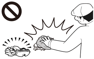
- An airbag or pretensioner may be activated by static electricity. To prevent this, be sure to touch a metal surface with your bare hands to discharge static electricity before performing this procedure.
- Do not perform this procedure indoors or on rough roads where safety cannot be ensured. Also, do not deploy SRS parts near residential areas.
- If this procedure is performed indoors or on rough roads where safety cannot be ensured, unforeseen injuries may occur. Also, the deployment noise creates a nuisance to nearby residents.
.png)
HINT:
When scrapping a vehicle equipped with an SRS or disposing of the lower No. 1 instrument panel airbag assembly, be sure to deploy the airbag first in accordance with the following procedure. If any abnormality occurs with the airbag deployment, contact the Service Department of the distributor.
2. DISPOSE OF LOWER NO. 1 INSTRUMENT PANEL AIRBAG ASSEMBLY (When Installed to Vehicle)
NOTICE:
- When disposing of a lower No. 1 instrument panel airbag assembly, never use the customer's vehicle to deploy the airbag.
- Be sure to perform the following procedure when deploying the airbag.
HINT:
Prepare an auxiliary battery as the power source to deploy the airbag.
| (a) Check the function of SST. Click here
SST: 09082-00700 |
|
.png)
(b) Refer to Precaution.
Click here .gif)
(c) Disconnect the cable from the negative (-) auxiliary battery terminal.
- for Gasoline Model
Click here
- for HEV Model
Click here
.png)
- Wait at least 90 seconds after disconnecting the cable from the negative (-) auxiliary battery terminal to disable the SRS system.
- If the airbag deploys for any reason, it may cause a serious accident.
(d) Remove the No. 1 instrument panel under cover sub-assembly.
Click here
HINT:
Perform the linked removal procedures until the No. 1 instrument panel under cover sub-assembly step.
| (e) Disconnect the airbag connector. NOTICE: When disconnecting any airbag connector, take care not to damage the airbag wire harness. HINT: Refer to How to Connect or Disconnect Airbag Connector: Click here |
|
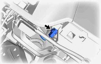
(f) Install SST.
- Do not deploy if the lower No. 1 instrument panel airbag assembly is loose.
- If deployed while the lower No. 1 instrument panel airbag assembly is loose, the lower No. 1 instrument panel airbag assembly may fly off and cause serious injuries.
| (1) After connecting the following SST to each other, connect them to the lower No. 1 instrument panel airbag assembly. SST: 09082-00700 SST: 09082-00802 09082-10801 09082-20801 NOTICE: To avoid damaging the SST connector or wire harness, do not lock the secondary lock of the twin lock. |
|
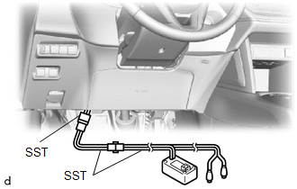
| (2) Move SST at least 10 m (32.8 ft.) away from the front side window of the vehicle. |
|
.png)
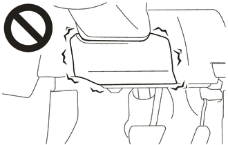
(3) While maintaining sufficient clearance for SST wire harness in the front side window, close all doors and windows of the vehicle.
CAUTION:
- Do not deploy with all the doors and door windows open.
- If deployed with all the doors and door windows open, dust and gas may enter the eyes or be breathed in.
.png)
NOTICE:
Take care not to damage the SST wire harness.
(4) Connect the red clip of SST to the positive (+) auxiliary battery terminal and the black clip of SST to the negative (-) auxiliary battery terminal.
(g) Deploy the airbag.
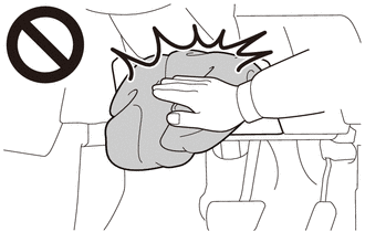
(1) Check that no one is inside the vehicle or within a 10 m (32.8 ft.) radius of the vehicle.
(2) Press the SST activation switch to deploy the airbag.
CAUTION:
- Do not deploy with people inside or around the vehicle.
- If deployed with people inside or around the vehicle, serious injuries may occur.
.png)
HINT:
The airbag is deployed as the LED of SST activation switch comes on.
(h) Remove the lower No. 1 instrument panel airbag assembly.
CAUTION:
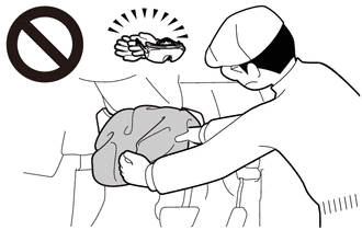
- The lower No. 1 instrument panel airbag assembly becomes extremely hot when the airbag is deployed, so do not touch it for at least 30 minutes after deployment.
- If not left alone for 30 minutes or more, burns may occur when touched.
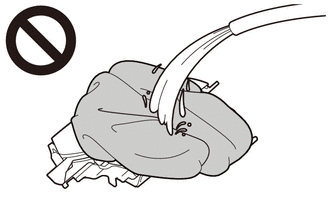
- Do not apply water etc. to a lower No. 1 instrument panel airbag assembly with a deployed airbag.
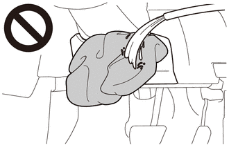
- If water is applied to the lower No. 1 instrument panel airbag assembly immediately after deployment, burns may occur from the resulting steam.
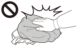
- Always wear safety glasses and gloves when handling a deployed lower No. 1 instrument panel airbag assembly.
- If the lower No. 1 instrument panel airbag assembly is touched without wearing safety glasses and gloves, hot parts may cause burns and dust may enter the eyes.
- After removal, quickly seal the lower No. 1 instrument panel airbag assembly in a plastic bag.
Click here
(i) Dispose of the lower No. 1 instrument panel airbag assembly.
(1) Place the lower No. 1 instrument panel airbag assembly in a plastic bag, tie it tightly and dispose of it according to local regulations.
CAUTION:
- The lower No. 1 instrument panel airbag assembly becomes extremely hot when the airbag is deployed, so do not touch it for at least 30 minutes after deployment.
- If not left alone for 30 minutes or more, burns may occur when touched.
- Do not apply water etc. to a lower No. 1 instrument panel airbag assembly with a deployed airbag.
- If water is applied to the lower No. 1 instrument panel airbag assembly immediately after deployment, burns may occur from the resulting steam.
- Always wear safety glasses and gloves when handling a deployed lower No. 1 instrument panel airbag assembly.
- If the lower No. 1 instrument panel airbag assembly is touched without wearing safety glasses and gloves, hot parts may cause burns and dust may enter the eyes.
- Never dispose of a lower No. 1 instrument panel airbag assembly with an undeployed airbag.
- If an undeployed lower No. 1 instrument panel airbag assembly is disposed of, and then deploys for any reason, unforeseen injuries may occur.
- Always wash your hands with water after completing the operation.
3. DISPOSE OF LOWER NO. 1 INSTRUMENT PANEL AIRBAG ASSEMBLY (When not Installed to Vehicle)
NOTICE:
Be sure to perform the following procedure when deploying the airbag.
HINT:
Prepare an auxiliary battery as the power source to deploy the airbag.
| (a) Check the function of SST. Click here
SST: 09082-00700 |
|
(b) Refer to Precaution.
Click here
(c) Disconnect the cable from the negative (-) auxiliary battery terminal.
- for Gasoline Model
Click here
- for HEV Model
Click here
- Wait at least 90 seconds after disconnecting the cable from the negative (-) auxiliary battery terminal to disable the SRS system.
- If the airbag deploys for any reason, it may cause a serious accident.
(d) Remove the lower No. 1 instrument panel airbag assembly.
Click here
.png)
|
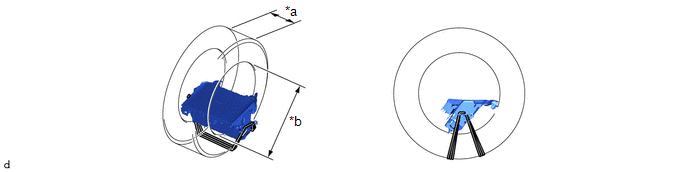
*a | Wire Diameter |
|
*b | Stripped Wire Cross Sectional Area |
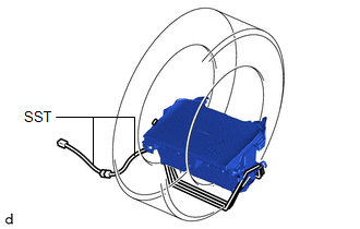
(e) Using braided wire, tie down the lower No. 1 instrument panel airbag assembly to an unneeded tire.
Wire:
Stripped Wire Cross Sectional Area
1.25 mm2 (0.0019 in.2) or more
CAUTION:
If the wire is too thin or an alternative object is used to tie down the lower No. 1 instrument panel airbag assembly, it may snap when the airbag is deployed. Always use a wire for vehicle use with a cross sectional area of at least 1.25 mm2 (0.0019 in.2).
HINT:
To calculate the cross sectional area of the stripped wire:
Cross sectional area = 3.14 x (Diameter)2 / 4
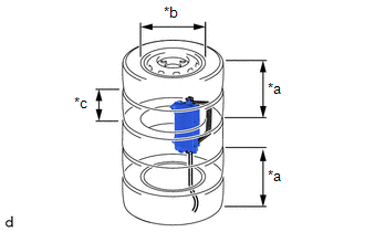
(1) Position the lower No. 1 instrument panel airbag assembly inside the tire with the airbag deployment side facing inward.
Minimum Tire Size:
Width
185 mm (7.28 in.)
Inner Diameter
360 mm (1.18 ft.)
|
*a | Width | *b |
Inner Diameter |
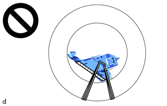
CAUTION:
- Make sure that the wires are tight. If there is slack in the wires, the lower No. 1 instrument panel airbag assembly may break loose when the airbag is deployed.
- Always tie down the lower No. 1 instrument panel airbag assembly with the airbag deployment side facing inside the tire.
.png)
Deployment Side
NOTICE:
The tire may be damaged by the airbag deployment, so use an unneeded tire.
(f) Install SST.
| (1) After connecting the following SST to each other, connect them to the lower No. 1 instrument panel airbag assembly. SST: 09082-00802 09082-10801 09082-20801 |
|
(g) Place the tires.
| (1) Place at least 2 tires under the tire to which the lower No. 1 instrument panel airbag assembly is tied. Minimum Tire Size: Width 185 mm (7.28 in.) Inner Diameter 360 mm (1.18 ft.) NOTICE: Do not place the SST connector under the tire because it could be damaged. |
|
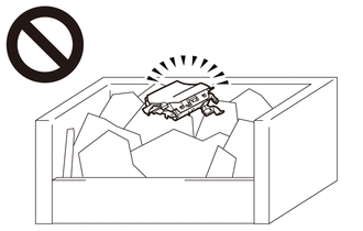
(2) Place at least 2 tires onto the tire to which the lower No. 1 instrument panel airbag assembly is tied. The top tire should have a wheel installed.
NOTICE:
The wheel and tires may be damaged by the airbag deployment, so use an unneeded wheel and tires.
| (3) Tie the tires together with 2 wires. CAUTION: Make sure that the wires are tight. Looseness in the wires will result in the tires breaking loose when the airbag is deployed. |
|
.png)
(h) Install SST.
| (1) Connect the SST connector. SST: 09082-00700 NOTICE: To avoid damaging the SST connector or wire harness, do not lock the secondary lock of the twin lock. Also, secure some slack for the SST wire harness inside the tire. |
|
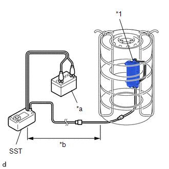
(2) Move SST at least 10 m (32.8 ft.) away from the airbag tied down to the tire.
(i) Deploy the airbag.
(1) Connect the red clip of SST to the positive (+) auxiliary battery terminal and the black clip of SST to the negative (-) auxiliary battery terminal.
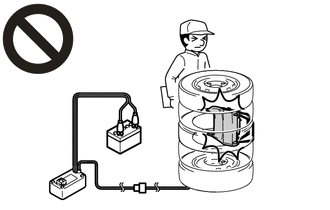
(2) Check that no one is within a 10 m (32.8 ft.) radius of the tire to which the lower No. 1 instrument panel airbag assembly is tied.
(3) Press the SST activation switch to deploy the airbag.
CAUTION:
- Do not deploy with people around the tire.
- If deployed with people around the tire, serious injuries may occur.
HINT:
The airbag is deployed as the LED of the SST activation switch comes on.
(j) Dispose of the lower No. 1 instrument panel airbag assembly.
CAUTION:
- The lower No. 1 instrument panel airbag assembly becomes extremely hot when the airbag is deployed, so do not touch it for at least 30 minutes after deployment.
- If not left alone for 30 minutes or more, burns may occur when touched.
- Do not apply water etc. to a lower No. 1 instrument panel airbag assembly with a deployed airbag.
- If water is applied to the lower No. 1 instrument panel airbag assembly immediately after deployment, burns may occur from the resulting steam.
- Always wear safety glasses and gloves when handling a deployed lower No. 1 instrument panel airbag assembly.
- If the lower No. 1 instrument panel airbag assembly is touched without wearing safety glasses and gloves, hot parts may cause burns and dust may enter the eyes.
- Never dispose of a lower No. 1 instrument panel airbag assembly with an undeployed airbag.
- If an undeployed lower No. 1 instrument panel airbag assembly is disposed of, and then deploys for any reason, unforeseen injuries may occur.
- Always wash your hands with water after completing the operation.
(1) Remove the lower No. 1 instrument panel airbag assembly from the tire.
(2) Place the lower No. 1 instrument panel airbag assembly in a plastic bag, tie it tightly, and dispose of it according to local regulations.


