Toyota Corolla Cross: Disassembly
DISASSEMBLY
CAUTION / NOTICE / HINT
COMPONENTS (DISASSEMBLY).png)
|
Procedure | Part Name Code |
.png) |
.png) |
 |
|---|---|---|---|---|---|
|
1 | ULTRASONIC SENSOR CLIP |
89348D |
|
- | - |
|
2 | REAR CENTER ULTRASONIC SENSOR |
89342A | - |
- | - |
|
3 | REAR CORNER ULTRASONIC SENSOR |
89342 | - |
- | - |
|
4 | REAR CENTER ULTRASONIC SENSOR RETAINER |
89C48B |
|
- | - |
|
5 | REAR CORNER ULTRASONIC SENSOR RETAINER |
89C48A |
|
- | - |
|
6 | NO. 9 FLOOR WIRE |
8216C | - |
- | - |
|
7 | REAR ULTRASONIC SENSOR CLIP |
89348Y | - |
- | - |
|
*A | w/ TOYOTA Parking Assist-sensor System |
- | - |
|
● | Non-reusable part |
- | - |
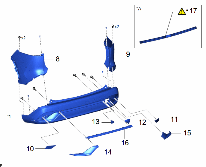
|
Procedure | Part Name Code |
.png) |
.png) |
 |
|---|---|---|---|---|---|
|
8 | REAR BUMPER UPPER COVER LH |
52166A | - |
- | - |
|
9 | REAR BUMPER UPPER COVER RH |
52165A | - |
- | - |
|
10 | REFLEX REFLECTOR ASSEMBLY LH |
81920 | - |
- | - |
|
11 | REFLEX REFLECTOR ASSEMBLY RH |
81910 | - |
- | - |
|
12 | REAR BUMPER PLATE RH |
52163A | - |
- | - |
|
13 | NO. 1 REAR BUMPER PLATE |
52162B | - |
- | - |
|
14 | REAR BUMPER SIDE MOULDING LH |
52753 | - |
- | - |
|
15 | REAR BUMPER SIDE MOULDING RH |
52752 | - |
- | - |
|
16 | REAR BUMPER BAR |
52151E | - |
- | - |
|
17 | REAR BUMPER PROTECTOR |
52581 |
|
- | - |
|
*1 | REAR BUMPER COVER |
- | - |
|
*A | w/ Protector |
- | - |
|
● | Non-reusable part |
- | - |
|
Procedure | Part Name Code |
.png) |
.png) |
 |
|---|---|---|---|---|---|
|
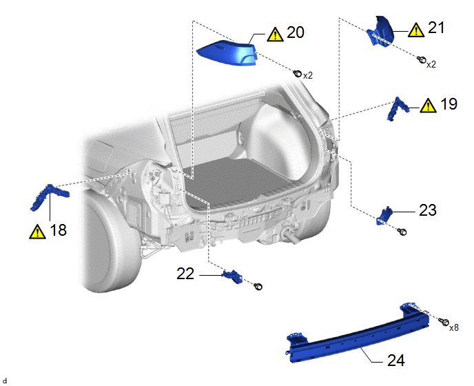
18 | REAR BUMPER SIDE RETAINER LH |
52576 |
|
- | - |
|
19 | REAR BUMPER SIDE RETAINER RH |
52575 |
|
- | - |
|
20 | REAR COMBINATION LIGHT ASSEMBLY LH |
81560 |
|
- | - |
|
21 | REAR COMBINATION LIGHT ASSEMBLY RH |
81550 |
|
- | - |
|
22 | REAR BUMPER UPPER RETAINER LH |
52563A | - |
- | - |
|
23 | REAR BUMPER UPPER RETAINER RH |
52562B | - |
- | - |
|
24 | REAR BUMPER REINFORCEMENT SUB-ASSEMBLY |
52023 | - |
- | - |
PROCEDURE
1. REMOVE ULTRASONIC SENSOR CLIP (w/ TOYOTA Parking Assist-sensor System)
.png) |
Click here |
2. REMOVE REAR CENTER ULTRASONIC SENSOR (w/ TOYOTA Parking Assist-sensor System)
3. REMOVE REAR CORNER ULTRASONIC SENSOR (w/ TOYOTA Parking Assist-sensor System)
Click here .gif)
4. REMOVE REAR CENTER ULTRASONIC SENSOR RETAINER (w/ TOYOTA Parking Assist-sensor System)
.png) |
Click here |
5. REMOVE REAR CORNER ULTRASONIC SENSOR RETAINER (w/ TOYOTA Parking Assist-sensor System)
.png) |
Click here |
6. REMOVE NO. 9 FLOOR WIRE (w/ TOYOTA Parking Assist-sensor System)
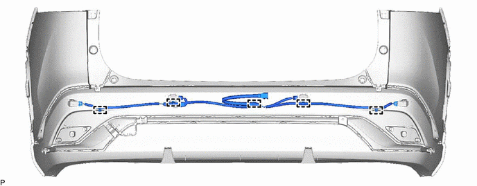
7. REMOVE REAR ULTRASONIC SENSOR CLIP (w/ TOYOTA Parking Assist-sensor System)
.png)
8. REMOVE REAR BUMPER UPPER COVER LH

9. REMOVE REAR BUMPER UPPER COVER RH
(a) Use the same procedure as for the LH side
10. REMOVE REFLEX REFLECTOR ASSEMBLY LH

11. REMOVE REFLEX REFLECTOR ASSEMBLY RH
(a) Use the same procedure as for the LH side
12. REMOVE REAR BUMPER PLATE RH

13. REMOVE NO. 1 REAR BUMPER PLATE

14. REMOVE REAR BUMPER SIDE MOULDING LH

15. REMOVE REAR BUMPER SIDE MOULDING RH

16. REMOVE REAR BUMPER BAR
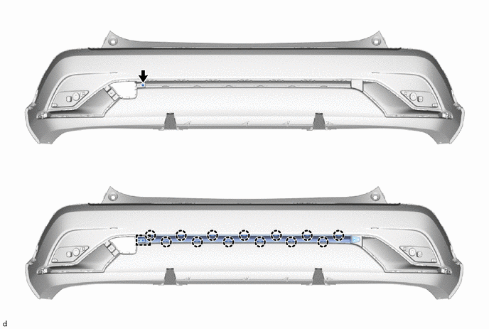
17. REMOVE REAR BUMPER PROTECTOR (w/ Protector)
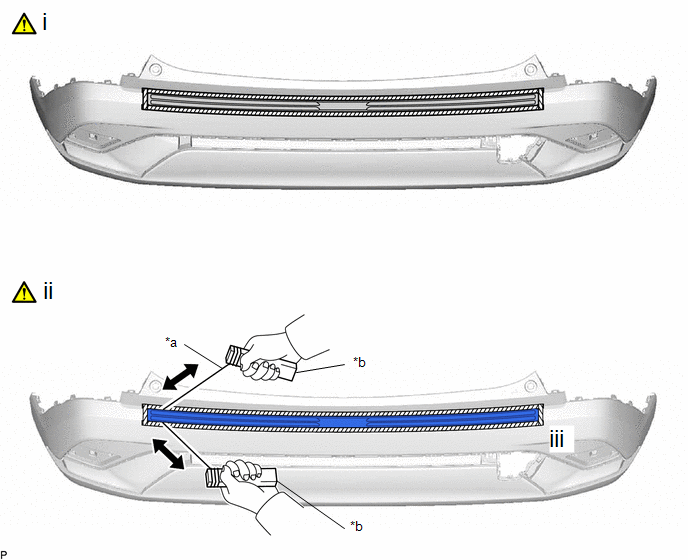
|
*a | Piano wire |
*b | Wooden Block |
(1) Apply protective tape around the rear bumper protector as shown in the illustration.
(2) Remove the rear bumper protector.
1. Insert a piano wire between the rear bumper assembly and rear bumper protector.
2. Tie objects that can serve as handles (for example, wooden blocks) to both wire ends.
3. Pull the piano wire and cut the double-sided tape that holds the rear bumper protector to the vehicle body to remove the rear bumper protector.
NOTICE:
Be careful not to damage the rear bumper assembly.
(3) Remove the protective tape.
18. REMOVE REAR BUMPER SIDE RETAINER LH
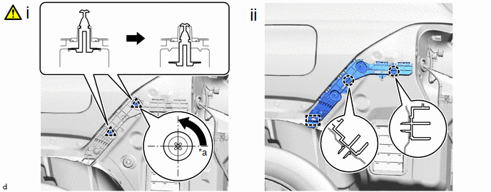
|
*a | 90° |
- | - |
(1) Using a screwdriver, turn the clip 90° and disengage the clips as shown in the illustration.
(2) Disengage the claws and guide to remove the rear bumper side retainer LH.
19. REMOVE REAR BUMPER SIDE RETAINER RH
(a) Use the same procedure as for the LH side
20. REMOVE REAR COMBINATION LIGHT ASSEMBLY LH
.png) |
Click here |
21. REMOVE REAR COMBINATION LIGHT ASSEMBLY RH
(a) Use the same procedure as for the LH side
22. REMOVE REAR BUMPER UPPER RETAINER LH
.png)
23. REMOVE REAR BUMPER UPPER RETAINER RH
(a) Use the same procedure as for the LH side
24. REMOVE REAR BUMPER REINFORCEMENT SUB-ASSEMBLY


