Toyota Corolla Cross: Crankshaft Position Sensor "A" No Signal (P033531)
DESCRIPTION
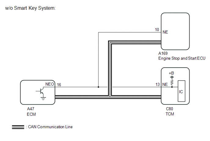
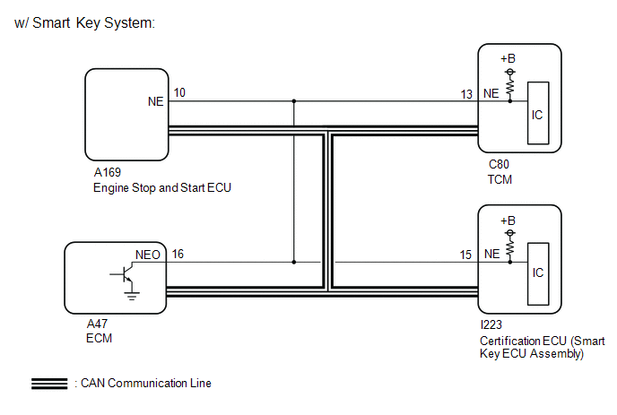
The TCM receives the engine speed signal from the ECM via CAN communication and direct line.
|
DTC No. |
Detection Item |
DTC Detection Condition |
Trouble Area |
MIL |
Memory |
Note |
|---|---|---|---|---|---|---|
|
P033531 |
Crankshaft Position Sensor "A" No Signal |
When the engine speed signal received from the ECM via CAN communication is 500 rpm or more, the signal received via direct line is 0 rpm for 5 seconds or more (1 trip detection logic). |
|
Comes on |
DTC stored |
SAE Code: P0335 |
MONITOR DESCRIPTION
The TCM detects malfunctions by comparing the engine speed signals received from the ECM via direct line and CAN communication.
If the TCM receives the engine speed signal via CAN communication but not via direct line, it will illuminate the MIL and store this DTC.
MONITOR STRATEGY
|
Related DTCs |
P0335: Crankshaft position sensor (CKP Sensor)/Verify pulse input |
|
Required sensors/Components (Main) |
ECM |
|
Required sensors/Components (Sub) |
CAN communication system |
|
Frequency of operation |
Continuous |
|
Duration |
5 sec. |
|
MIL operation |
Immediate |
|
Sequence of operation |
None |
TYPICAL ENABLING CONDITIONS
|
Auxiliary battery voltage |
8 V or more |
|
Ignition switch |
ON |
|
Starter |
OFF |
|
Lost Communication with ECM/PCM (U0100) (Pending / MIL) |
Not detected |
|
Following condition is met |
3 sec. or more |
|
- Ignition switch |
ON |
|
- Auxiliary battery voltage |
10 V or more |
|
Engine speed (Communication data from ECM) |
500 rpm or more |
TYPICAL MALFUNCTION THRESHOLDS
|
Crankshaft position sensor (CKP Sensor) revolution |
0 rpm or less |
COMPONENT OPERATING RANGE
|
Crankshaft position sensor (CKP Sensor) revolution |
500 rpm or more |
CONFIRMATION DRIVING PATTERN
HINT:
- After repairs have been completed, clear the DTCs and then check that the vehicle has returned to normal by performing the following All Readiness check procedure.
- When clearing the permanent DTCs, refer to the Clear Permanent DTC procedure.
Click here
.gif)
- Clear the DTCs (even if no DTCs are stored, perform the clear DTC procedure).
- Turn the ignition switch off and wait for 2 minutes or more.
- Turn the ignition switch to ON and turn the GTS on.
- Start the engine and wait for 5 seconds or more. [*1]
HINT:
[*1]: Normal judgment procedure.
The normal judgment procedure is used to complete DTC judgment and also used when clearing permanent DTCs.
- Enter the following menus: Powertrain / Transmission / Utility / All Readiness.
- Input the DTC: P033531.
- Check the DTC judgment result.
GTS Display
Description
NORMAL
- DTC judgment completed
- System normal
ABNORMAL
- DTC judgment completed
- System abnormal
INCOMPLETE
- DTC judgment not completed
- Perform driving pattern after confirming DTC enabling conditions
N/A
- Unable to perform DTC judgment
- Number of DTCs which do not fulfill DTC preconditions has reached ECU memory limit
HINT:
- If the judgment result shows NORMAL, the system is normal.
- If the judgment result shows ABNORMAL, the system has a malfunction.
- If the judgment result shows INCOMPLETE or N/A, perform the normal judgment procedure again.
WIRING DIAGRAM
CAUTION / NOTICE / HINT
NOTICE:
- Perform the universal trip to clear permanent DTCs.
Click here
- Perform registration and/or initialization when parts related to the continuously
variable transaxle system are replaced.
Click here
- Check that no DTCs are stored after performing initialization.
Click here
HINT:
- If no problem is found by this diagnostic troubleshooting procedure, check for problems by referring to the engine mechanical section.
- Read freeze frame data using the GTS. The TCM records vehicle and driving condition information as freeze frame data the moment a DTC is stored. When troubleshooting, freeze frame data can help determine if the vehicle was moving or stationary, if the engine was warmed up or not, if the air fuel ratio was lean or rich, and other data from the time the malfunction occurred.
DATA LIST
HINT:
The engine speed may be indicated as zero despite the engine running normally. This is caused by the NE signal not being received from the crankshaft position sensor. Alternatively, the engine speed may be indicated as lower than the actual engine speed if the crankshaft position sensor output voltage is insufficient.
(a) Start the engine.
(b) Enter the following menus:
(c) According to the display on the GTS, read the Data List.
Powertrain > Transmission > Data List|
Tester Display |
Measurement Item |
Range |
Normal Condition |
Diagnostic Note |
|---|---|---|---|---|
|
Engine Speed |
Engine speed |
Min.: 0 rpm Max.: 16383 rpm |
750 to 850 rpm: Engine idling (shift lever in P, engine warmed up and A/C off) |
When the crankshaft position sensor is malfunctioning, "Engine Speed" is approximately 0 rpm or varies greatly from the actual engine speed. |
|
Tester Display |
|---|
|
Engine Speed |
PROCEDURE
|
1. |
CHECK DTC OUTPUT (STOP AND START SYSTEM (P033562)) |
(a) Check for stop and start system DTCs.
Powertrain > Stop and Start > Trouble Codes|
Result |
Proceed to |
|---|---|
|
DTCs are not output |
A |
|
DTC P033562 are output |
B |
| B | .gif) |
GO TO STOP AND START SYSTEM |
|
.gif)
|
2. |
CHECK VEHICLE CONDITION |
(a) Choose the model to be inspected.
|
Result |
Proceed to |
|---|---|
|
w/o Smart Key System |
A |
|
w/ Smart Key System |
B |
| B | |
GO TO STEP 9 |
|
|
3. |
READ VALUE USING GTS (ENGINE SPEED) |
(a) Enter the following menus:
(b) According to the display on the GTS, read the Data List.
Powertrain > Transmission > Data List|
Tester Display |
Measurement Item |
Range |
Normal Condition |
Diagnostic Note |
|---|---|---|---|---|
|
Engine Speed |
Engine speed |
Min.: 0 rpm Max.: 16383 rpm |
750 to 850 rpm: Engine idling (shift lever in P, engine warmed up and A/C off) |
When the crankshaft position sensor is malfunctioning, "Engine Speed" is approximately 0 rpm or varies greatly from the actual engine speed. |
|
Tester Display |
|---|
|
Engine Speed |
OK:
The GTS display changes correctly in response to the engine speed.
| OK | |
CHECK FOR INTERMITTENT PROBLEMS Click here Click here |
|
|
4. |
CHECK HARNESS AND CONNECTOR (TCM - ECM) |
(a) Disconnect the A47 ECM connector.
(b) Disconnect the C80 TCM connector.
(c) Measure the resistance according to the value(s) in the table below.
Standard Resistance:
|
Tester Connection |
Condition |
Specified Condition |
|---|---|---|
|
A47-16 (NEO) - C80-13 (NE) |
Always |
Below 1 Ω |
|
A47-16 (NEO) or C80-13 (NE) - Body ground and other terminals |
Always |
10 kΩ or higher |
(d) Connect the C80 TCM connector.
(e) Connect the A47 ECM connector.
| NG | |
REPAIR OR REPLACE HARNESS OR CONNECTOR |
|
|
5. |
REPLACE TCM |
Click here
|
|
6. |
PERFORM REGISTRATION AND INITIALIZATION |
(a) Perform Registration and Initialization.
for Registration: Click here
for Initialization: Click here
|
|
7. |
CONFIRM WHETHER MALFUNCTION HAS BEEN SUCCESSFULLY REPAIRED (P033531) |
(a) Start the engine and wait for 5 seconds or more.
(b) Enter the following menus:
(c) Read the DTCs.
Powertrain > Transmission > Trouble Codes|
Result |
Proceed to |
|---|---|
|
DTCs are not output |
A |
|
DTC P033531 is output |
B |
| A | |
END |
|
|
8. |
REPLACE ECM |
Click here
| NEXT | |
PERFORM REGISTRATION AND INITIALIZATION for Registration: Click here for Initialization: Click here |
|
9. |
CHECK DTC OUTPUT (SMART KEY SYSTEM (P033562)) |
(a) Check for smart key system DTCs.
|
Result |
Proceed to |
|---|---|
|
DTCs are not output |
A |
|
P033562 is output |
B |
| B | |
GO TO SMART KEY SYSTEM |
|
|
10. |
CHECK HARNESS AND CONNECTOR (TCM - ECM) |
(a) Disconnect the A47 ECM connector.
(b) Disconnect the C80 TCM connector.
(c) Measure the resistance according to the value(s) in the table below.
Standard Resistance:
|
Tester Connection |
Condition |
Specified Condition |
|---|---|---|
|
A47-16 (NEO) - C80-13 (NE) |
Always |
Below 1 Ω |
|
A47-16 (NEO) or C80-13 (NE) - Body ground and other terminals |
Always |
10 kΩ or higher |
(d) Connect the C80 TCM connector.
(e) Connect the A47 ECM connector.
| NG | |
REPAIR OR REPLACE HARNESS OR CONNECTOR |
|
|
11. |
REPLACE TCM |
Click here
| NEXT | |
PERFORM REGISTRATION AND INITIALIZATION for Registration: Click here for Initialization: Click here |


