Toyota Corolla Cross: Crankshaft Position Sensor
Removal
REMOVAL
CAUTION / NOTICE / HINT
COMPONENTS (REMOVAL)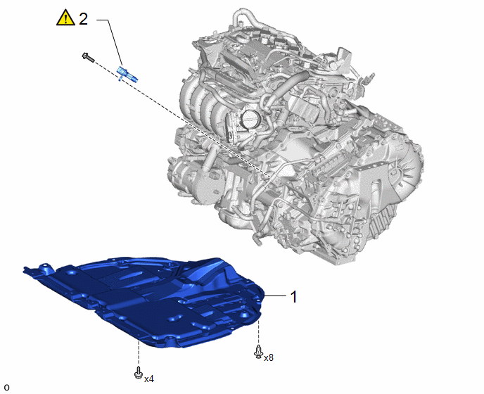
|
Procedure | Part Name Code |
.png) |
.png) |
 |
|---|---|---|---|---|---|
|
1 | NO. 1 ENGINE UNDER COVER ASSEMBLY |
51410 | - |
- | - |
|
2 | CRANKSHAFT POSITION SENSOR |
11401G |
|
- | - |
CAUTION / NOTICE / HINT
NOTICE:
This procedure includes the removal of small-head bolts. Refer to Small-Head Bolts of Basic Repair Hint to identify the small-head bolts.
Click here .gif)
PROCEDURE
1. REMOVE NO. 1 ENGINE UNDER COVER ASSEMBLY
Click here
2. REMOVE CRANKSHAFT POSITION SENSOR
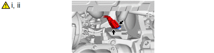
(1) Disconnect the crank position sensor connector.
(2) Using an 8 mm socket wrench, remove the bolt and crank position sensor from the cylinder block sub-assembly.
NOTICE:
If the crank position sensor has been struck or dropped, replace it.
Installation
INSTALLATION
CAUTION / NOTICE / HINT
COMPONENTS (INSTALLATION)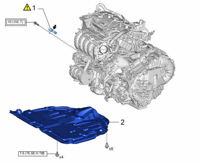
|
Procedure | Part Name Code |
.png) |
.png) |
 |
|---|---|---|---|---|---|
|
1 | CRANKSHAFT POSITION SENSOR |
11401G |
|
- | - |
|
2 | NO. 1 ENGINE UNDER COVER ASSEMBLY |
51410 | - |
- | - |
.png) |
TOYOTA genuine engine oil |
- | - |
.png) |
Tightening torque for "Major areasinvolving basic vehicle performance suchas moving/turning/stopping" : N*m(kgf*cm, ft.*lbf) |
.png) |
N*m (kgf*cm, ft.*lbf): Specified torque |
CAUTION / NOTICE / HINT
NOTICE:
This procedure includes the installation of small-head bolts. Refer to Small-Head Bolts of Basic Repair Hint to identify the small-head bolts.
Click here .gif)
PROCEDURE
1. INSTALL CRANKSHAFT POSITION SENSOR
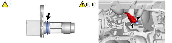
(1) Apply a light coat of engine oil to the O-ring of the crank position sensor.
NOTICE:
If reusing the crank position sensor, be sure to inspect the O-ring.
(2) Using an 8 mm socket wrench, install the crank position sensor to the cylinder block sub-assembly with the bolt.
Torque:
10 N·m {102 kgf·cm, 7 ft·lbf}
NOTICE:
- If the crank position sensor has been struck or dropped, replace it.
- Make sure that the O-ring is not cracked or moved out of place when installing the crank position sensor.
(3) Connect the crank position sensor connector.
2. INSTALL NO. 1 ENGINE UNDER COVER ASSEMBLY
Click here


