Toyota Corolla Cross: Coolant Thermostat (Coolant Temperature Below Thermostat Regulating Temperature) (P012800,P012807)
DESCRIPTION
The ECM uses the engine coolant temperature sensor, installed to the water outlet, to monitor the operation of the thermostat.
|
DTC No. | Detection Item |
DTC Detection Condition | Trouble Area |
MIL | Note |
|---|---|---|---|---|---|
|
P012800 | Coolant Thermostat (Coolant Temperature Below Thermostat Regulating Temperature) |
All of the following conditions are met for 5 seconds or more (2 trip detection logic):
|
| Comes on |
|
| P012807 |
Coolant Thermostat (Coolant Temperature Below Thermostat Regulating Temperature) Mechanical Failure |
All of the following conditions are met for 3 times (2 trip detection logic):
|
| Comes on |
|
MONITOR DESCRIPTION
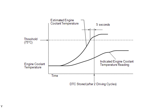
P012800: Judgment by Simulated Engine Coolant Temperature
The ECM estimates the engine coolant temperature based on the starting temperature, engine loads, and engine speeds. The ECM then compares the estimated temperature with the actual engine coolant temperature. When the estimated engine coolant temperature reaches 75°C (167°F), the ECM checks the actual engine coolant temperature. If the actual engine coolant temperature is less than 75°C (167°F), the ECM interprets this as a malfunction in the thermostat or the engine cooling system and stores the DTC.
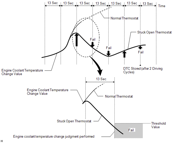
P012807: Judgment by Engine Coolant Temperature Change at High Vehicle Speed
When the vehicle is being driven between 65 and 128 km/h (40.625 and 80 mph) and the monitoring conditions are met, the change in engine coolant temperature is monitored. The amount of change is judged to be normal or abnormal every 13 seconds, in order to monitor the thermostat operation. If the engine coolant temperature changes more than the threshold, the thermostat is judged as normal, but if it changes less than the threshold, the thermostat is judged to be malfunctioning. If an abnormal judgment is made 3 times, the ECM will illuminate the MIL and store a DTC.
MONITOR STRATEGY
|
Related DTCs | P0128: Coolant thermostat (judgment by simulated engine coolant temperature) P0128: Coolant thermostat (judgment by engine coolant temperature change at high vehicle speed) |
|
Required Sensors/Components (Main) | Thermostat Engine coolant temperature sensor |
|
Required Sensors/Components (Related) |
Intake air temperature sensor Vehicle speed sensor |
|
Frequency of Operation | Once per driving cycle: Judgment by simulated engine coolant temperature Continuous: Judgment by engine coolant temperature change at high vehicle speed |
|
Duration | 320 seconds: Judgment by simulated engine coolant temperature -: Judgment by engine coolant temperature change at high vehicle speed |
|
MIL Operation | 2 driving cycles |
|
Sequence of Operation | None |
TYPICAL ENABLING CONDITIONS
ALL|
Monitor runs whenever the following DTCs are not stored |
P0010, P1360, P1362, P1364, P1366, P2614 (Motor drive VVT system control module) P0011 (VVT system - advance) P0012 (VVT system - retard) P0013 (Exhaust VVT oil control solenoid) P0014 (Exhaust VVT system - advance) P0015 (Exhaust VVT system - retard) P0016 (VVT system - misalignment) P0017 (Exhaust VVT system - misalignment) P0031, P0032, P101D (Air fuel ratio sensor (sensor 1) heater) P014C, P014D, P015A, P015B, P2195, P2196, P2237, P2238, P2239, P2252, P2253 (Air fuel ratio sensor (sensor 1)) P0087, P0088, P0191, P0192, P0193 (Fuel pressure sensor (for high pressure side)) P0101, P0102, P0103 (Mass air flow meter) P0107, P0108 (Manifold absolute pressure) P0111, P0112, P0113 (Intake air temperature sensor) P0116, P0117, P0118 (Engine coolant temperature sensor) P0121, P0122, P0123, P0222, P0223, P2135 (Throttle position sensor) P0171, P0172 (Fuel system) P0201, P0202, P0203, P0204, P062D, P21CF, P21D0, P21D1, P21D2 (Fuel injector) P0300, P0301, P0302, P0303, P0304 (Misfire) P0335, P0337, P0338 (Crankshaft position sensor) P0340, P0342, P0343 (Camshaft position sensor) P0365, P0367, P0368 (Exhaust camshaft position sensor) P0400 (EGR system) P0401 (EGR system (closed)) P0489, P0490 (EGR control circuit) P0500 (Vehicle speed sensor) P107B, P107C, P107D (Fuel pressure sensor (for low pressure side)) P11EA, P11EC, P11ED, P11EE, P11EF, P219A, P219C, P219D, P219E, P219F (Air-fuel ratio imbalance) P1235 (High pressure fuel pump circuit) |
|
Auxiliary battery voltage | 11 V or higher |
|
Either of the following conditions is met |
1 or 2 |
| 1. All of the following conditions are met |
(a), (b) and (c) |
| (a) Engine coolant temperature at engine start - Intake air temperature (for mass air flow meter sub-assembly) at engine start |
-15 to 7°C (-27 to 12.6°F) |
|
(b) Engine coolant temperature at engine start |
-10 to 56°C (14 to 133°F) |
|
(c) Intake air temperature (for mass air flow meter sub-assembly) at engine start |
-10 to 56°C (14 to 133°F) |
|
2. All of the following conditions are met |
(d), (e) and (f) |
| (d) Engine coolant temperature at engine start - Intake air temperature (for mass air flow meter sub-assembly) at engine start |
Higher than 7°C (12.6°F) |
|
(e) Engine coolant temperature at engine start |
56°C (133°F) or less |
| (f) Intake air temperature (for mass air flow meter sub-assembly) at engine start |
-10°C (14°F) or higher |
|
Accumulated time at vehicle speed of 128 km/h (80 mph) or more |
Less than 20 seconds |
|
During that all of the following conditions are met |
13 seconds or more |
| Auxiliary battery voltage |
11 V or higher |
| Engine coolant temperature at engine start |
-10°C (14°F) or higher |
|
Intake air temperature at engine start |
-10°C (14°F) or higher |
|
Target engine coolant flow by electric water pump |
1.5 L/min or more |
| Vehicle speed |
65 to 128 km/h (40.625 to 80 mph) |
TYPICAL MALFUNCTION THRESHOLDS
P012800: Judgment by Simulated Engine Coolant Temperature|
Duration that both of the following conditions are met |
5 seconds or more |
| (a) Estimated engine coolant temperature |
75°C (167°F) or higher |
|
(b) Engine coolant temperature sensor output |
Less than 75°C (167°F) |
|
Malfunction counter | 3 times or more |
|
Malfunction counter is incremented when following conditions are met |
A and B |
| A. Average engine coolant temperature change (vary with current engine coolant temperature, estimated ambient air temperature, intake air mass and vehicle speed) |
Less than -0.1°C/sec (-0.18°F/sec) |
|
B. Engine coolant temperature is satisfied throughout this period |
Less than 75°C (167°F) |
CONFIRMATION DRIVING PATTERN
HINT:
- After repair has been completed, clear the DTC and then check that the vehicle has returned to normal by performing the following All Readiness check procedure.
Click here
.gif)
.gif)
- When clearing the permanent DTCs, refer to the "CLEAR PERMANENT DTC" procedure.
Click here
.gif)
.gif)

- Stop the engine and allow it to soak.
- Connect the GTS to the DLC3.
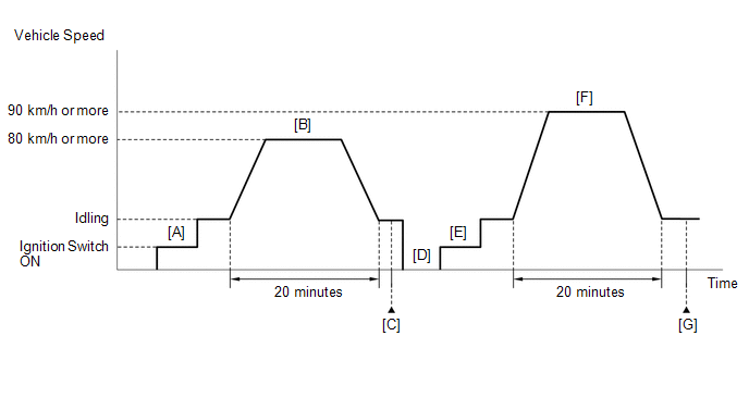
- Turn the ignition switch to ON [A].
- Turn the GTS on.
- Enter the following menus: Powertrain / Engine / Data List / Coolant Temperature and Intake Air Temperature.
- Check that the value of the Data List item Coolant Temperature is 56°C (133°F) or less and the value of the Data List item Intake Air Temperature is between 0 and 35°C (32 and 95°F).
- Set the heater control to MAX HOT with fresh air mode selected and turn the A/C off.
- Start the engine and drive the vehicle at 80 km/h (50 mph) or more for 20 minutes [B].
CAUTION:
When performing the confirmation driving pattern, obey all speed limits and traffic laws.
- After the value of the Data List item Coolant Temperature stabilizes, check that it is 75°C (167°F) or higher.
HINT:
If the value of the Data List item Coolant Temperature is less than 75°C (167°F) while driving the vehicle at 80 km/h (50 mph), inspect the cooling system and thermostat.
- Enter the following menus: Powertrain / Engine / Trouble Codes [C].
- Read the pending DTCs.
HINT:
- If a pending DTC is output, the system is malfunctioning.
- If a pending DTC is not output, perform the following procedure.
- Enter the following menus: Powertrain / Engine / Utility / All Readiness.
- Input the DTC: P012800 or P012807.
- Check the DTC judgment result.
GTS Display
Description
NORMAL
- DTC judgment completed
- System normal
ABNORMAL
- DTC judgment completed
- System abnormal
INCOMPLETE
- DTC judgment not completed
- Perform driving pattern after confirming DTC enabling conditions
HINT:
- If the judgment result is NORMAL, the system is normal.
- If the judgment result is ABNORMAL, the system has a malfunction.
- If the judgment result is INCOMPLETE, If the judgment result is INCOMPLETE, perform steps [D] through [G].
- With the engine stopped, leave the vehicle outside overnight [D].
- Turn the ignition switch to ON [E].
- Turn the GTS on.
- Enter the following menus: Powertrain / Engine / Data List / Coolant Temperature.
- Check that the value of the Data List item Coolant Temperature is 25°C (77°F) or less.
- Start the engine and drive the vehicle at 90 km/h (56 mph) or more for 20 minutes [F].
CAUTION:
When performing the confirmation driving pattern, obey all speed limits and traffic laws.
- Enter the following menus: Powertrain / Engine / Trouble Codes [G].
- Read the pending DTCs.
HINT:
- If a pending DTC is output, the system is malfunctioning.
- If a pending DTC is not output, perform the following procedure.
- Enter the following menus: Powertrain / Engine / Utility / All Readiness.
- Input the DTC: P012800 or P012807.
- Check the DTC judgment result again.
GTS Display
Description
NORMAL
- DTC judgment completed
- System normal
ABNORMAL
- DTC judgment completed
- System abnormal
INCOMPLETE
- DTC judgment not completed
- Perform driving pattern after confirming DTC enabling conditions
HINT:
- If the judgment result is NORMAL, the system is normal.
- If the judgment result is ABNORMAL, the system has a malfunction.
- [D] to [G]: Normal judgment procedure.
The normal judgment procedure is used to complete DTC judgment and also used when clearing permanent DTCs.
- When clearing the permanent DTCs, do not disconnect the cable from the auxiliary battery terminal or attempt to clear the DTCs during this procedure, as doing so will clear the universal trip and normal judgment histories.
CAUTION / NOTICE / HINT
HINT:
- When the DTC is output, check the engine coolant temperature using the GTS. Enter the following menus: Powertrain / Engine / Data List / Coolant Temperature. If the Coolant Temperature value is lower than the actual engine coolant temperature, the engine coolant temperature sensor circuit may be malfunctioning. In this case, check the wire harnesses and connectors (and those connections) between the ECM and the engine coolant temperature sensor first.
- Read freeze frame data using the GTS. The ECM records vehicle and driving condition information as freeze frame data the moment a DTC is stored. When troubleshooting, freeze frame data can help determine if the vehicle was moving or stationary, if the engine was warmed up or not, if the air fuel ratio was lean or rich, and other data from the time the malfunction occurred.
PROCEDURE
|
1. | CHECK ANY OTHER DTCS OUTPUT (IN ADDITION TO DTC P012800 OR P012807) |
(a) Read the DTCs.
Powertrain > Engine > Trouble Codes|
Result | Proceed to |
|---|---|
|
DTC P012800 or P012807 is output |
A |
| DTC P012800 or P012807 and other DTCs are output |
B |
HINT:
If any DTCs other than P012800 or P012807 are output, troubleshoot those DTCs first.
| B |
.gif) | GO TO DTC CHART |
|
| 2. |
CHECK ENGINE COOLING SYSTEM |
(a) Check for defects in the engine cooling system that might cause the system to be too cold, such as abnormal cooling fan operation or any modifications.
| NG | .gif) | REPAIR OR REPLACE ENGINE COOLING SYSTEM |
|
| 3. |
INSPECT WATER INLET WITH THERMOSTAT SUB-ASSEMBLY |
(a) Inspect the water inlet with thermostat sub-assembly (thermostat opening temperature).
Click here .gif)
| NG | .gif) | REPLACE WATER INLET WITH THERMOSTAT SUB-ASSEMBLY |
|
| 4. |
INSPECT ENGINE COOLANT TEMPERATURE SENSOR |
Click here .gif)
HINT:
Perform "Inspection After Repair" after replacing the engine coolant temperature sensor.
Click here .gif)
| OK | .gif) | REPLACE ECM
|
| NG | .gif) | REPLACE ENGINE COOLANT TEMPERATURE SENSOR
|

.gif)

