Toyota Corolla Cross: Check Mode Procedure
Toyota Corolla Cross (2022-2026) Service Manual / Drivetrain / K120 (cvt) / Continuously Variable Transaxle System / Check Mode Procedure
CHECK MODE PROCEDURE
DESCRIPTION
(a) Check mode has a higher sensitivity to malfunctions and can detect malfunctions that cannot be detected in normal mode. Check mode can also detect all of the malfunctions that can be detected in normal mode. In check mode, DTCs are stored with 1-trip detection logic.
NOTICE:
- All DTCs and freeze frame data will be cleared if: 1) the GTS is used to change the TCM from normal mode to check mode or vice versa; or 2) during check mode, the ignition switch is turned from ON to ACC or off.
- Before changing to check mode, make a note of the DTCs and freeze frame data.
CHECK MODE PROCEDURE
(a) Make sure that the following conditions are met:
- Auxiliary battery voltage is 11 V or higher.
- The throttle valve is fully closed.
- The shift lever is in P or N.
- The A/C switch is off.
(b) Enter the following menus:
Powertrain > Transmission > Utility|
Tester Display |
|---|
|
Check Mode |
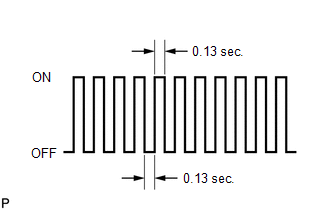
(c) Check that the MIL flashes as shown in the illustration.
(d) Start the engine. The MIL should turn off after the engine starts.
(e) Simulate the conditions of the malfunction described by the customer.
(f) Using the GTS, check for DTCs and freeze frame data.


