Toyota Corolla Cross: Brake System Control Module "A" System Voltage Line Internal Electronic Failure (C117A49,C137BA2)
DESCRIPTION
If a malfunction is detected in the power supply circuit, the skid control ECU (brake actuator assembly) stores this DTC and the fail-safe function prohibits ABS, brake assist, regenerative braking, etc. operation.
This DTC is stored when the +BS terminal voltage meets one of the DTC detection conditions due to a malfunction in the power supply or charging circuit such as the auxiliary battery or DC/DC converter circuit, etc.
The DTC is cleared when the +BS terminal voltage returns to normal.
|
DTC No. |
Detection Item |
DTC Detection Condition |
Trouble Area |
MIL |
DTC Output from |
Note |
|---|---|---|---|---|---|---|
|
C117A49 |
Brake System Control Module "A" System Voltage Line Internal Electronic Failure |
The vehicle speed is 15 km/h (9 mph) or more and the +BS terminal voltage is 9.6 V or more, the skid control ECU (brake actuator assembly) turns on more than one valve at the same time within a short period of time and the valve relay supply voltage drop exceeds the threshold.* |
|
Comes on |
Brake/EPB |
|
|
C137BA2 |
Brake System Control Module "A" System Voltage System Voltage Low |
Any of the following is detected:
|
|
Does not come on |
Brake/EPB |
Output ECU: Skid control ECU (brake actuator assembly) |
*: The skid control ECU (brake actuator assembly) monitors the resistance of the power source line at the +BS terminal. A malfunction is detected when an abnormality occurs in the +BS terminal wire harness or its connection and the skid control ECU (brake actuator assembly) determines that the wiring resistance at the +BS terminal exceeds the standard resistance.
MONITOR DESCRIPTION
When the vehicle speed is more than a certain value, the supply voltage of the skid control ECU (brake actuator assembly) is a certain value or more, the brake pedal is not depressed, and the resistance of the solenoid supply voltage line exceeds a certain value a certain number of times, the skid control ECU (brake actuator assembly) illuminates the MIL and stores this DTC.
MONITOR STRATEGY
|
Related DTCs |
C117A: Supply voltage line test |
|
Required Sensors/Components(Main) |
Skid control ECU (brake actuator assembly) |
|
Required Sensors/Components(Related) |
Speed sensor Skid control ECU (brake actuator assembly) Stop light switch assembly |
|
Frequency of Operation |
During initial checking |
|
Duration |
- |
|
MIL Operation |
Immediately |
|
Sequence of Operation |
None |
TYPICAL ENABLING CONDITIONS
|
Monitor runs whenever the following DTCs are not stored |
TMC's intellectual property |
|
Other conditions belong to TMC's intellectual property |
- |
TYPICAL MALFUNCTION THRESHOLDS
|
TMC's intellectual property |
- |
COMPONENT OPERATING RANGE
|
TMC's intellectual property |
- |
CONFIRMATION DRIVING PATTERN
NOTICE:
When performing the normal judgment procedure, make sure that the driver door is closed and is not opened at any time during the procedure.
HINT:
- After repair has been completed, clear the DTC and then check that the vehicle has returned to normal by performing the following All Readiness check procedure.
- When clearing the permanent DTCs, refer to the "CLEAR PERMANENT DTC" procedure.
- Connect the GTS to the DLC3.
- Turn the ignition switch to ON and turn the GTS on.
- Clear the DTCs (even if no DTCs are stored, perform the clear DTC procedure).
- Turn the ignition switch off.
- Turn the ignition switch to ON (READY) and turn the GTS on.
- Drive the vehicle at 15 km/h (9 mph) or more for 1 second. [*]
HINT:
[*]: Normal judgment procedure.
The normal judgment procedure is used to complete DTC judgment and also used when clearing permanent DTCs.
- Enter the following menus: Chassis / Brake/EPB* / Utility / All Readiness.
*: Electric Parking Brake System
- Check the DTC judgment result.
HINT:
- If the judgment result shows NORMAL, the system is normal.
- If the judgment result shows ABNORMAL, the system has a malfunction.
- If the judgment result shows INCOMPLETE, perform driving pattern again.
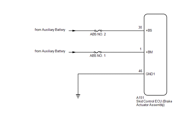
WIRING DIAGRAM
CAUTION / NOTICE / HINT
NOTICE:
- Inspect the fuses for circuits related to this system before performing the following procedure.
- Before performing troubleshooting, make sure to confirm that the auxiliary
battery voltage is normal.
Click here
.gif)
PROCEDURE
|
1. |
CHECK HARNESS AND CONNECTOR (POWER SOURCE TERMINAL) |
|
(a) Make sure that there is no looseness at the locking part and the connecting part of the connector. OK: The connector is securely connected. |
|
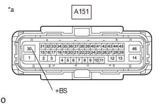
(b) Disconnect the A151 skid control ECU (brake actuator assembly) connector.
(c) Check both the connector case and the terminals for deformation and corrosion.
OK:
No deformation or corrosion.
(d) Measure the voltage according to the value(s) in the table below.
Standard Voltage:
|
Tester Connection |
Condition |
Specified Condition |
|---|---|---|
|
A151-30 (+BS) - Body ground |
Always |
11 to 14 V |
| NG | .gif)
|
REPAIR OR REPLACE HARNESS OR CONNECTOR |
|
.gif)
|
2. |
CHECK HARNESS AND CONNECTOR (POWER SOURCE TERMINAL) |
|
(a) Make sure that there is no looseness at the locking part and the connecting part of the connector. OK: The connector is securely connected. |
|
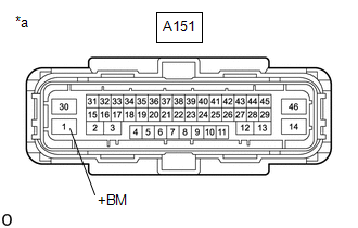
(b) Disconnect the A151 skid control ECU (brake actuator assembly) connector.
(c) Check both the connector case and the terminals for deformation and corrosion.
OK:
No deformation or corrosion.
(d) Measure the voltage according to the value(s) in the table below.
Standard Voltage:
|
Tester Connection |
Condition |
Specified Condition |
|---|---|---|
|
A151-1 (+BM) - Body ground |
Always |
11 to 14 V |
| OK |
|
REPLACE BRAKE ACTUATOR ASSEMBLY |
| NG |
|
REPAIR OR REPLACE HARNESS OR CONNECTOR |
READ NEXT:
 Brake Pressure Sensor "A" / Brake Switch "A" Signal Compare Failure (C117B62)
DESCRIPTION
The skid control ECU (brake actuator assembly) receives stop
light switch assembly signals and uses them to determine whether or not the brakes
are applied.
When the brake pedal is d
Target Brake Pressure Sensor "A" for Force Blending Signal Malfunction (C117C00,C117D00)
DESCRIPTION
DTC No.
Detection Item
DTC Detection Condition
Trouble Area
MIL
DTC Output from
Note
C117C00
Electronic Brake Booster Control Module "A" System Internal Failure (C121F04,C14C9A3)
DESCRIPTION
If there is a malfunction in the power source circuit, the electric
brake booster (brake booster with master cylinder assembly) stores a DTC, and ABS,
brake assist, regenerative braki
SEE MORE:
 Initialization
INITIALIZATION SERVO MOTOR INITIALIZATION (a) Press the OFF switch.
(b) According to the GTS display, perform servo motor initialization. Body Electrical > Air Conditioner > Utility
Tester Display Servomotor Initialization
HINT: When initialization is started, the AUTO switc
Calibration
CALIBRATION
ADJUST PARKING ASSIST MONITOR SYSTEM
(a) The parking assist monitor system can be adjusted using diagnostic
mode.
(b) If the following operations are performed, it is necessary
to perform adjustments and checks using diagnostic mode.
Part Name
Operation
