Toyota Corolla Cross: Brake Pressure Sensor "A" / Brake Switch "A" Signal Compare Failure (C117B62)
DESCRIPTION
The skid control ECU (brake actuator assembly) receives stop light switch assembly signals and uses them to determine whether or not the brakes are applied.
When the brake pedal is depressed and no signal is received from the stop light switch assembly, this DTC is output.
|
DTC No. |
Detection Item |
DTC Detection Condition |
Trouble Area |
MIL |
DTC Output from |
Note |
|---|---|---|---|---|---|---|
|
C117B62 |
Brake Pressure Sensor "A" / Brake Switch "A" Signal Compare Failure |
Either of the following is detected when the vehicle speed of 3 km/h (2 mph) or more:
|
|
Comes on |
Brake/EPB |
|
MONITOR DESCRIPTION
C117B (Case 1):- When the vehicle is being driven at a certain speed or more, 60 seconds
or more have elapsed after operation of the brake pedal, and any of the
following conditions continue for a certain amount of time, the skid control
ECU (brake actuator assembly) illuminates the MIL and stores this DTC.
- The master cylinder pressure after the offset calibration is a certain value or more.
- The master cylinder pressure before the offset calibration is a certain value or more.
- The vehicle speed is a certain value or more and the master cylinder pressure is less than a certain value.
- The stop light switch assembly is off, and the master cylinder pressure is a certain value or more.
- When the vehicle is being driven at a certain speed or more, the brake pedal is not operated, the ABS is not operating, and the master cylinder pressure exceeds a certain value for a certain amount of time, the skid control ECU (brake actuator assembly) illuminates the MIL and stores this DTC.
MONITOR STRATEGY
|
Related DTCs |
C117B (Case 1): Stop light switch / pressure sensor rationality monitoring (logic 1) C117B (Case 2): Stop light switch / pressure sensor rationality monitoring (logic 2) |
|
Required Sensors/Components(Main) |
Skid control ECU (brake actuator assembly) Speed sensor Stop light switch assembly |
|
Required Sensors/Components(Related) |
Skid control ECU (brake actuator assembly) Speed sensor Stop light switch assembly |
|
Frequency of Operation |
Continuous |
|
Duration |
3 seconds |
|
MIL Operation |
2 driving cycles |
|
Sequence of Operation |
None |
TYPICAL ENABLING CONDITIONS
|
Monitor runs whenever the following DTCs are not stored |
TMC's intellectual property |
|
Other conditions belong to TMC's intellectual property |
- |
TYPICAL MALFUNCTION THRESHOLDS
|
TMC's intellectual property |
- |
COMPONENT OPERATING RANGE
|
TMC's intellectual property |
- |
CONFIRMATION DRIVING PATTERN
NOTICE:
When performing the normal judgment procedure, make sure that the driver door is closed and is not opened at any time during the procedure.
HINT:
- After repair has been completed, clear the DTC and then check that the vehicle has returned to normal by performing the following All Readiness check procedure.
- When clearing the permanent DTCs, refer to the "CLEAR PERMANENT DTC" procedure.
- Connect the GTS to the DLC3.
- Turn the ignition switch to ON and turn the GTS on.
- Clear the DTCs (even if no DTCs are stored, perform the clear DTC procedure).
- Turn the ignition switch off.
- Turn the ignition switch to ON (READY) and turn the GTS on.
- Drive the vehicle at 3 km/h (2 mph) or more for 3 seconds. [*]
HINT:
[*]: Normal judgment procedure.
The normal judgment procedure is used to complete DTC judgment and also used when clearing permanent DTCs.
- Enter the following menus: Chassis / Brake/EPB* / Utility / All Readiness.
*: Electric Parking Brake System
- Check the DTC judgment result.
HINT:
- If the judgment result shows NORMAL, the system is normal.
- If the judgment result shows ABNORMAL, the system has a malfunction.
- If the judgment result shows INCOMPLETE, perform driving pattern again.
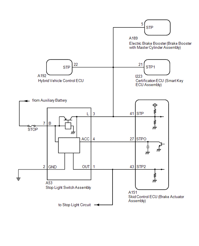
WIRING DIAGRAM
CAUTION / NOTICE / HINT
NOTICE:
Inspect the fuses for circuits related to this system before performing the following procedure.
PROCEDURE
|
1. |
READ VALUE USING GTS (MASTER CYLINDER SENSOR) |
(a) Check the Data List using the GTS.
Chassis > Brake/EPB > Data List|
Tester Display |
Measurement Item |
Range |
Normal Condition |
Diagnostic Note |
|---|---|---|---|---|
|
Master Cylinder Sensor 1 |
Master cylinder pressure sensor pressure (value detected by ECU) |
Min.: -1.00 MPa, Max.: 23.99 MPa |
Brake pedal released: -1.00 to 0.00 MPa |
Reading increases when brake pedal is depressed |
|
Tester Display |
|---|
|
Master Cylinder Sensor 1 |
(b) Check the value of Data List item Master Cylinder Sensor 1 when the brake pedal is released.
OK:
The value of Data List item Master Cylinder Sensor 1 when the brake pedal is released is less than 0.15 MPa.
| NG | .gif)
|
GO TO STEP 4 |
|
.gif)
|
2. |
CHECK HARNESS AND CONNECTOR (STOP LIGHT SWITCH ASSEMBLY SIGNAL INPUT CIRCUIT) |
|
(a) Make sure that there is no looseness at the locking part and the connecting part of the connector. OK: The connector is securely connected. |
|
(b) Disconnect the A151 skid control ECU (brake actuator assembly) connector.
(c) Check both the connector case and the terminals for deformation and corrosion.
OK:
No deformation or corrosion.
(d) Measure the voltage according to the value(s) in the table below.
Standard Voltage:
|
Tester Connection |
Condition |
Specified Condition |
|---|---|---|
|
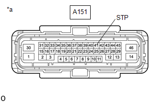
A151-41 (STP) - Body ground |
Brake pedal depressed |
11 to 14 V |
| OK |
|
REPLACE BRAKE ACTUATOR ASSEMBLY |
|
|
3. |
CHECK HARNESS AND CONNECTOR (STOP LIGHT SWITCH ASSEMBLY - BRAKE ACTUATOR ASSEMBLY) |
(a) Make sure that there is no looseness at the locking part and the connecting part of the connector.
OK:
The connector is securely connected.
(b) Disconnect the A151 skid control ECU (brake actuator assembly) connector.
(c) Disconnect the A53 stop light switch assembly connector.
(d) Check both the connector case and the terminals for deformation and corrosion.
OK:
No deformation or corrosion.
(e) Measure the resistance according to the value(s) in the table below.
Standard Resistance:
|
Tester Connection |
Condition |
Specified Condition |
|---|---|---|
|
A53-3 (L) - A151-41 (STP) |
Always |
Below 1 Ω |
|
A53-3 (L) or A151-41 (STP) - Body ground and other terminals |
Always |
10 kΩ or higher |
| OK |
|
REPLACE STOP LIGHT SWITCH ASSEMBLY |
| NG |
|
REPAIR OR REPLACE HARNESS OR CONNECTOR |
|
4. |
CHECK DTC |
(a) Read the DTCs using the GTS.
Chassis > Brake/EPB > Trouble Codes|
Result |
Proceed to |
|---|---|
|
C117B62 and C05401C, C054028, C054029, C054031, C054049 and/or C054096 are output simultaneously |
A |
|
C117B62 is output |
B |
| A |
|
REPAIR CIRCUITS INDICATED BY OUTPUT DTCS |
| B |
|
GO TO BRAKE SYSTEM Refer to "Brake drag" of problem symptoms table. Inspect brake system: Click here
Inspect brake pedal free play: Click here
|
.gif)
READ NEXT:
 Target Brake Pressure Sensor "A" for Force Blending Signal Malfunction (C117C00,C117D00)
DESCRIPTION
DTC No.
Detection Item
DTC Detection Condition
Trouble Area
MIL
DTC Output from
Note
C117C00
Electronic Brake Booster Control Module "A" System Internal Failure (C121F04,C14C9A3)
DESCRIPTION
If there is a malfunction in the power source circuit, the electric
brake booster (brake booster with master cylinder assembly) stores a DTC, and ABS,
brake assist, regenerative braki
Electronic Brake Booster Control Module "A" Signal Compare Failure (C121F62)
DESCRIPTION
When the self-check function of the electric brake booster (brake
booster with master cylinder assembly) detects an internal circuit malfunction,
this DTC is stored.
DTC N
SEE MORE:
 Immobiliser Amp Missing Message (B278E87)
DESCRIPTION A transponder key amplifier is built into the certification ECU (smart key ECU assembly).
When a communication malfunction occurs with the transponder key amplifier inside the certification ECU (smart key ECU assembly), this DTC is stored.
DTC No. Detection Item
DTC Detect
Removal
REMOVAL CAUTION / NOTICE / HINT COMPONENTS (REMOVAL)
Procedure Part Name Code
1 PRECAUTION
-
- -
2 SERVICE PLUG GRIP
G3834 -
- -
3 REMOVE CONNECTOR COVER ASSEMBLY
-
