Toyota Corolla Cross: Brake Pedal Switch "A" Circuit Open (C004013)
DESCRIPTION
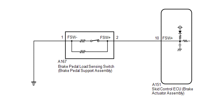
The brake pedal load sensing switch (brake pedal support assembly) turns on when the brake pedal is depressed with a force exceeding a predetermined level.
The skid control ECU (brake actuator assembly) uses this circuit to detect if the brake pedal is depressed or not.
|
DTC No. |
Detection Item |
DTC Detection Condition |
Trouble Area |
|---|---|---|---|
|
C004013 |
Brake Pedal Switch "A" Circuit Open |
An open or short in the brake pedal load sensing switch circuit continues for 0.5 seconds or more. |
|
WIRING DIAGRAM
CAUTION / NOTICE / HINT
HINT:
When C117B62, P057112 and/or P057113 is output together with C004013, inspect and repair the trouble areas indicated by C117B62, P057112 and/or P057113 first.
- C117B62: Click here
.gif)
- P057112: Click here
- P057113: Click here
PROCEDURE
|
1. |
READ VALUE USING GTS (BRAKE PEDAL LOAD SENSING SW) |
(a) Check the Data List using the GTS.
Chassis > Brake/EPB > Data List|
Tester Display |
Measurement Item |
Range |
Normal Condition |
Diagnostic Note |
|---|---|---|---|---|
|
Brake Pedal Load Sensing SW |
Brake pedal load sensing switch (brake pedal support assembly) |
OFF / ON |
OFF: Brake pedal load sensing switch (brake pedal support assembly) OFF ON: Brake pedal load sensing switch (brake pedal support assembly) ON |
- |
(b) Check that the brake pedal load sensing switch display observed on the GTS changes according to brake pedal operation.
OK:
The GTS displays ON or OFF according to brake pedal operation.
| NG | .gif)
|
GO TO STEP 4 |
|
.gif)
|
2. |
CLEAR DTC |
(a) Clear the DTCs.
Chassis > Brake/EPB > Clear DTCs(b) Turn the ignition switch off.
|
|
3. |
RECONFIRM DTC |
(a) Based on the Freeze Frame Data and interview with the customer, attempt to reproduce the conditions when the malfunction occurred.
(b) Check if the same DTC is output.
Chassis > Brake/EPB > Trouble Codes|
Result |
Proceed to |
|---|---|
|
C004013 is not output |
A |
|
C004013 is output |
B |
| A |
|
USE SIMULATION METHOD TO CHECK |
| B |
|
REPLACE BRAKE ACTUATOR ASSEMBLY |
|
4. |
INSPECT BRAKE PEDAL LOAD SENSING SWITCH |
|
(a) Turn the ignition switch off. |
|
(b) Make sure that there is no looseness at the locking part and the connecting part of the connector.
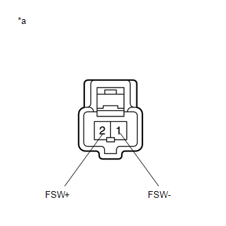
(c) Disconnect the A167 brake pedal load sensing switch (brake pedal support assembly) connector.
NOTICE:
- Do not remove the brake pedal load sensing switch from the brake pedal support assembly.
- When there is a malfunction in the brake pedal load sensing switch, replace the brake pedal support assembly.
(d) Measure the resistance according to the value(s) in the table below.
Standard Resistance:
|
Tester Connection |
Condition |
Specified Condition |
|---|---|---|
|
2 (FSW+) - 1 (FSW-) |
Brake pedal load sensing switch off (Brake pedal depressed) |
950 to 1050 Ω |
|
2 (FSW+) - 1 (FSW-) |
Brake pedal load sensing switch on (Brake pedal released) |
203 to 223 Ω |
| NG |
|
REPLACE BRAKE PEDAL SUPPORT ASSEMBLY |
|
|
5. |
CHECK HARNESS AND CONNECTOR (BRAKE ACTUATOR ASSEMBLY - BRAKE PEDAL LOAD SENSING SWITCH) |
(a) Make sure that there is no looseness at the locking part and the connecting part of the connector.
(b) Disconnect the A151 skid control ECU (brake actuator assembly) connector.
(c) Measure the resistance according to the value(s) in the table below.
Standard Resistance:
|
Tester Connection |
Condition |
Specified Condition |
|---|---|---|
|
A151-10 (FSW+) - A167-2 (FSW+) |
Always |
Below 1 Ω |
|
A151-10 (FSW+) - Body ground |
Always |
10 kΩ or higher |
|
A167-2 (FSW+) - Body ground |
Always |
10 kΩ or higher |
|
A167-1 (FSW-) - Body ground |
1 minute or more after disconnecting the cable from the negative (-) auxiliary battery terminal |
Below 1 Ω |
| OK |
|
REPLACE BRAKE ACTUATOR ASSEMBLY |
| NG |
|
REPAIR OR REPLACE HARNESS OR CONNECTOR |


