Toyota Corolla Cross: Back Door Motor Internal Electronic Failure (B222049)
DESCRIPTION
This DTC is stored when the multiplex network door ECU detects a malfunction of the motor built-into the power back door unit assembly set LH or power back door unit assembly set RH.
|
DTC No. | Detection Item |
DTC Detection Condition | Trouble Area |
|---|---|---|---|
|
B222049 | Back Door Motor Internal Electronic Failure |
Malfunction of motor built into the power back door unit assembly set LH or power back door unit assembly set RH detected |
|
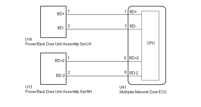
WIRING DIAGRAM
CAUTION / NOTICE / HINT
NOTICE:
If the multiplex network door ECU has been removed and installed or replaced, or if any of the connectors has been disconnected, initialize the power back door system.
Click here .gif)
PROCEDURE
| 1. |
CLEAR DTC |
(a) Clear the DTCs.
Body Electrical > Back Door > Clear DTCs
|
.gif)
| 2. |
CHECK FOR DTC |
(a) Check for DTCs.
Body Electrical > Back Door > Trouble Codes|
Result | Proceed to |
|---|---|
|
B222049 is output | A |
|
B222049 is not output |
B |
| B |
.gif) | USE SIMULATION METHOD TO CHECK |
|
| 3. |
INSPECT POWER BACK DOOR UNIT ASSEMBLY SET LH |
(a) Fully open the back door.
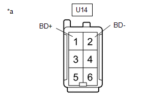
| (b) Disconnect the power back door unit assembly set LH connector. |
|
(c) Measure the resistance according to the value(s) in the table below.
Standard Resistance:
|
Tester Connection | Condition |
Specified Condition |
|---|---|---|
|
U14-1 (BD+) - Body ground |
Always | 10 kΩ or higher |
|
U14-2 (BD-) - Body ground |
Always | 10 kΩ or higher |
|
U14-1 (BD+) - U14-2 (BD-) |
Always | Below 1 MΩ |
| NG | | REPLACE POWER BACK DOOR UNIT ASSEMBLY SET LH |
|
| 4. |
INSPECT POWER BACK DOOR UNIT ASSEMBLY SET RH |
(a) Fully open the back door.
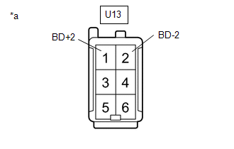
| (b) Disconnect the power back door unit assembly set RH connector. |
|
(c) Measure the resistance according to the value(s) in the table below.
Standard Resistance:
|
Tester Connection | Condition |
Specified Condition |
|---|---|---|
|
U13-1 (BD+2) - Body ground |
Always | 10 kΩ or higher |
|
U13-2 (BD-2) - Body ground |
Always | 10 kΩ or higher |
|
U13-1 (BD+2) - U13-2 (BD-2) |
Always | Below 1 MΩ |
| NG | | REPLACE POWER BACK DOOR UNIT ASSEMBLY SET RH |
|
| 5. |
CHECK HARNESS AND CONNECTOR (MULTIPLEX NETWORK DOOR ECU - POWER BACK DOOR UNIT ASSEMBLY SET LH) |
(a) Disconnect the U41 multiplex network door ECU connector.
(b) Disconnect the U14 power back door unit assembly set LH connector.
(c) Measure the resistance according to the value(s) in the table below.
Standard Resistance:
|
Tester Connection | Condition |
Specified Condition |
|---|---|---|
|
U41-1 (BD+) - U14-1 (BD+) |
Always | Below 1 Ω |
|
U41-3 (BD-) - U14-2 (BD-) |
Always | Below 1 Ω |
|
U41-1 (BD+) or U14-1 (BD+) - Body ground |
Always | 10 kΩ or higher |
|
U41-3 (BD-) or U14-2 (BD-) - Body ground |
Always | 10 kΩ or higher |
| NG | | REPAIR OR REPLACE HARNESS OR CONNECTOR |
|
| 6. |
CHECK HARNESS AND CONNECTOR (MULTIPLEX NETWORK DOOR ECU - POWER BACK DOOR UNIT ASSEMBLY SET RH) |
(a) Disconnect the U41 multiplex network door ECU connector.
(b) Disconnect the U13 power back door unit assembly set RH connector.
(c) Measure the resistance according to the value(s) in the table below.
Standard Resistance:
|
Tester Connection | Condition |
Specified Condition |
|---|---|---|
|
U41-6 (BD+2) - U13-1 (BD+2) |
Always | Below 1 Ω |
|
U41-8 (BD-2) - U13-2 (BD-2) |
Always | Below 1 Ω |
|
U41-6 (BD+2) or U13-1 (BD+2) - Body ground |
Always | 10 kΩ or higher |
|
U41-8 (BD-2) or U13-2 (BD-2) - Body ground |
Always | 10 kΩ or higher |
| OK | | REPLACE MULTIPLEX NETWORK DOOR ECU |
| NG | | REPAIR OR REPLACE HARNESS OR CONNECTOR |


