Toyota Corolla Cross: Antenna Coil Circuit Voltage Out of Range (B27841C)
DESCRIPTION
When an open or short circuit is detected in the transponder key amplifier coil built into the power switch, the certification ECU (smart key ECU assembly) stores this DTC. This DTC is also stored as a history DTC.
|
DTC No. | Detection Item |
DTC Detection Condition | Trouble Area |
Note |
|---|---|---|---|---|
| B27841C |
Antenna Coil Circuit Voltage Out of Range |
The transponder key amplifier coil built into the power switch is open (see below) or shorted (determined by communication with certification ECU (smart key ECU assembly)). (1 trip detection logic*) |
| DTC output confirmation operation:
|
- *: Only output while a malfunction is present.
|
Vehicle Condition when Malfunction Detected |
Fail-safe Operation when Malfunction Detected |
|---|---|
|
Hybrid control system cannot be started when transmitter battery is depleted by holding electrical key transmitter sub-assembly near power switch and pressing and holding power switch with shift position in P |
- |
|
DTC No. | Data List and Active Test |
|---|---|
|
B27841C | - |
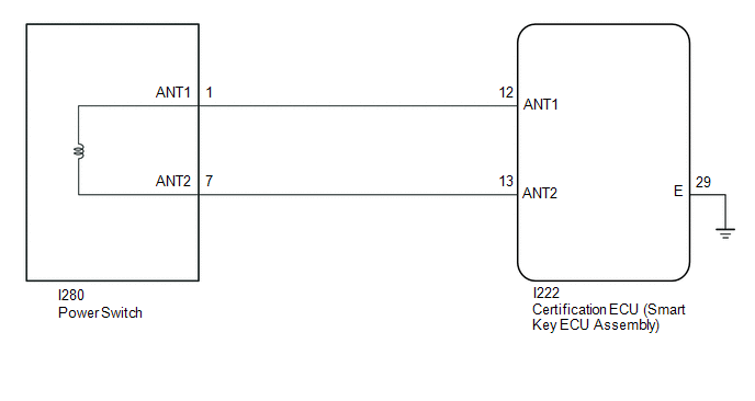
WIRING DIAGRAM
CAUTION / NOTICE / HINT
NOTICE:
- When using the GTS with the ignition switch off, connect the GTS to the DLC3 and turn a courtesy light switch on and off at intervals of 1.5 seconds or less until communication between the GTS and the vehicle begins.
Then select Model Code "KEY REGIST" under manual mode and enter the following menus: Body Electrical / Start Key(CAN). While using the GTS, periodically turn a courtesy light switch on and off at intervals of 1.5 seconds or less to maintain communication between the GTS and the vehicle.
- The smart key system (for Start Function) uses the LIN communication system and CAN communication system. Inspect the communication function by following How to Proceed with Troubleshooting. Troubleshoot the smart key system (for Start Function) after confirming that the communication systems are functioning properly.
Click here
.gif)
- Before replacing the certification ECU (smart key ECU assembly), refer to Registration.
Click here
- After performing repairs, confirm that no DTCs are output by performing "DTC Output Confirmation Operation".
PROCEDURE
|
1. | CHECK CONNECTION OF CONNECTOR |
(a) Check that the connectors are properly connected to the power switch and certification ECU (smart key ECU assembly).
OK:
Connectors are properly connected.
| NG | .gif) | CONNECT CONNECTORS PROPERLY |
|
.gif)
| 2. |
CHECK HARNESS AND CONNECTOR (CERTIFICATION ECU (SMART KEY ECU ASSEMBLY) - POWER SWITCH AND BODY GROUND) |
(a) Disconnect the I222 certification ECU (smart key ECU assembly) connector.
(b) Disconnect the I280 power switch connector.
(c) Measure the resistance according to the value(s) in the table below.
Standard Resistance:
|
Tester Connection | Condition |
Specified Condition |
|---|---|---|
|
I222-12 (ANT1) - I280-1 (ANT1) |
Always | Below 1 Ω |
|
I222-12 (ANT1) or I280-1 (ANT1) - Other terminals and body ground |
Always | 10 kΩ or higher |
|
I222-13 (ANT2) - I280-7 (ANT2) |
Always | Below 1 Ω |
|
I222-13 (ANT2) or I280-7 (ANT2) - Other terminals and body ground |
Always | 10 kΩ or higher |
| NG | | REPAIR OR REPLACE HARNESS OR CONNECTOR |
|
| 3. |
CHECK CERTIFICATION ECU (SMART KEY ECU ASSEMBLY) |
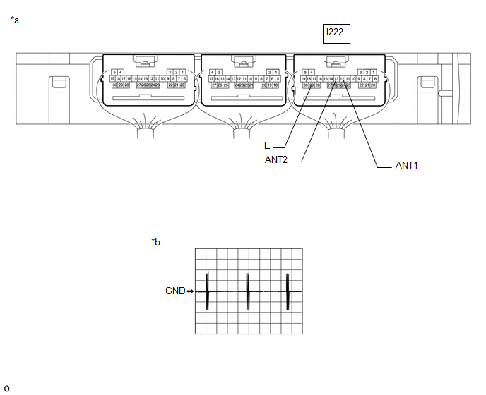
(a) Connect the I222 certification ECU (smart key ECU assembly) connector.
(b) Using an oscilloscope, check the waveform.
|
*a | Component with harness connected (Certification ECU (Smart Key ECU Assembly)) |
*b | Waveform |
OK:
|
Tester Connection | Condition |
Tool Setting | Specified Condition |
|---|---|---|---|
|
I222-12 (ANT1) - I222-29 (E) |
Ignition switch off, electrical key transmitter sub-assembly not in cabin, within 30 seconds of power switch pressed |
5 V/DIV., 200 ms./DIV. |
Pulse generation (See waveform) |
|
I222-13 (ANT2) - I222-29 (E) |
Ignition switch off, electrical key transmitter sub-assembly not in cabin, within 30 seconds of power switch pressed |
5 V/DIV., 200 ms./DIV. |
Pulse generation (See waveform) |
| OK | | REPLACE POWER SWITCH |
| NG | | REPLACE CERTIFICATION ECU (SMART KEY ECU ASSEMBLY) |
READ NEXT:
 ID-BOX Component Internal Failure (B278D96)
DESCRIPTION When the certification ECU (smart key ECU assembly) detects an input signal indicating that the vehicle is equipped with an ID code box even though the ID code box is not registered, the c
Immobiliser Amp Missing Message (B278E87)
DESCRIPTION A transponder key amplifier is built into the certification ECU (smart key ECU assembly).
When a communication malfunction occurs with the transponder key amplifier inside the certificat
ID-BOX Calibration / Parameter Memory Failure (B279046)
DESCRIPTION When an internal malfunction occurs in the ID code box (immobiliser code ECU), the certification ECU (smart key ECU assembly) stores this DTC.
DTC No. Detection Item
DTC Detec
SEE MORE:
 Problem Symptoms Table
PROBLEM SYMPTOMS TABLE
NOTICE:
If the power window regulator motor assembly has been replaced with a new one, initialize the power window control system.
Click here
If the main body ECU (multiplex network body ECU) is replaced, refer to Service Bulletin.
HINT:
Use the table below to help
Power Source Mode does not Change to ON (IG and ACC)
DESCRIPTION When the ignition switch cannot be turned to ACC or ON, interior verification may be abnormal or there may be a malfunction in the ACC relay or IG relay circuit. If interior verification cannot be performed, the certification ECU (smart key ECU assembly) may be malfunctioning or communic
