Toyota Corolla Cross Owners & Service Manuals

Toyota Corolla Cross: Tongue Plate Stopper

Components

COMPONENTS

ILLUSTRATION
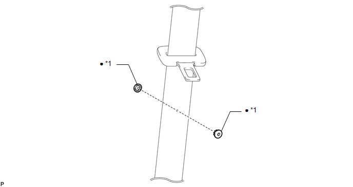
*1

TONGUE PLATE STOPPER

-

-

Non-reusable part

-

-

Replacement

REPLACEMENT

PROCEDURE

1. REMOVE TONGUE PLATE STOPPER

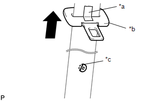
(a) Slide the tongue plate above the installation position of the tongue plate stopper, and temporarily hold it with adhesive tape.

*a

Adhesive Tape

*b

Tongue Plate

*c

Broken Tongue Plate Stopper

(b) Remove any pieces of the original tongue plate stopper in the belt webbing with a pair of pliers.

NOTICE:

Be careful not to damage the belt webbing during repair.

2. INSTALL TONGUE PLATE STOPPER

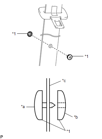
(a) Position a new tongue plate stopper in the hole of the belt webbing.

HINT:

Make sure that the installation direction of the tongue plate stopper is as shown in the illustration.

*1

Tongue Plate Stopper

*a

Male

*b

Female

*c

Belt Webbing

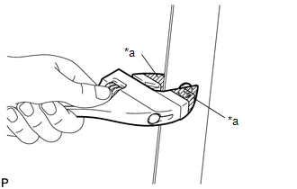
(b) Hold the tongue plate stopper in the hole of the belt webbing using an adjustable wrench, and turn the adjustment screw of the adjustable wrench by hand to compress the tongue plate stopper.

NOTICE:

  • When using the adjustable wrench, make sure to position the male and female parts of the tongue plate stopper parallel to each other.
  • Do not use pliers to compress the pin of the tongue plate stopper. They may damage the tongue plate stopper and belt webbing.

HINT:

Tape the jaws of the adjustable wrench before use.

*a

Protective Tape

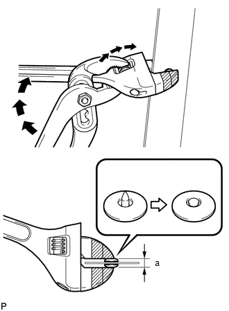
(c) When the adjustment screw of the adjustable wrench can no longer be turned by hand, tighten the adjustment screw using a pair of adjustable joint pliers until the tongue plate stopper thickness is 4.5 to 5.0 mm (0.177 to 0.197 in.). (Refer to the illustrations.)

Standard Clearance

Area

Measurement

a

4.5 to 5.0 mm (0.177 to 0.197 in.)

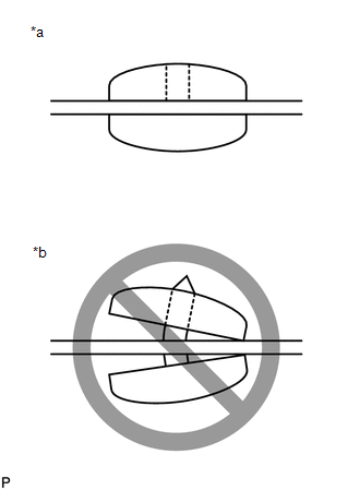
(d) Make sure that the pin of male side of the tongue plate stopper has expanded evenly in the hole of the female part and is firmly held to the belt webbing. (Refer to the illustrations.)

*a

Correct

*b

Incorrect

    READ NEXT:

     Supplemental Restraint Systems

     Airbag System

     Precaution

    PRECAUTION CAUTION: Failure to carry out service procedures in the correct sequence could cause SRS parts to unexpectedly deploy and possibly lead to serious injuries. Furthermore, if a mistake

    SEE MORE:

     Diagnostic Trouble Code Chart

    DIAGNOSTIC TROUBLE CODE CHART Front Camera System DTC No. Detection Item DTC Output from Link B150E94 Instrument Panel Cluster (IPC) Control Module Unexpected Operation Front Recognition Camera

     Front Passenger Side Power Window does not Operate with Front Passenger Side Power Window Switch

    DESCRIPTION When the ignition switch is ON, the power window regulator motor assembly (for front passenger door) is operated by the power window regulator switch assembly. The power window regulator motor assembly (for front passenger door) has motor, regulator, and ECU functions. WIRING DIAGRAM Cl

    © 2020-2025 Copyright www.tcorollacross.com