Toyota Corolla Cross: Terminals Of Ecu
TERMINALS OF ECU
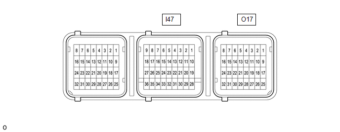
AIRBAG ECU ASSEMBLY
|
Terminal No. | Terminal Symbol |
Destination |
| I47-26 |
CANH | CAN communication line |
|
I47-27 | CANL |
CAN communication line |
|
I47-32 | E2 |
Ground |
| I47-33 |
E1 | Ground |
|
I47-34 | P-AB |
Passenger airbag OFF indicator (Map light assembly) |
|
I47-35 | PAON |
Passenger airbag ON indicator (Map light assembly) |
|
I47-36 | IGR |
A/BAG-IGR fuse |
|
O17-18 | GNDR |
Passenger seat buckle switch (Front seat inner belt assembly RH) |
|
O17-24 | SVC |
- Front occupant classification sensor LH (Front Seat Cushion Spring Sub-assembly RH)
- Rear occupant classification sensor LH (Front Seat Cushion Spring Sub-assembly RH)
|
| O17-27 |
RBE+ | Passenger seat buckle switch (Front seat inner belt assembly RH) |
|
O17-31 | SGD |
- Front occupant classification sensor LH (Front Seat Cushion Spring Sub-assembly RH)
- Rear occupant classification sensor LH (Front Seat Cushion Spring Sub-assembly RH)
|
| O17-32 |
SIG |
- Front occupant classification sensor LH (Front Seat Cushion Spring Sub-assembly RH)
- Rear occupant classification sensor LH (Front Seat Cushion Spring Sub-assembly RH)
|
READ NEXT:
DTC CHECK / CLEAR DTC CHECK (a) Check for DTCs (Test Failed / Pending / Confirmed). Body Electrical > SRS Airbag > Trouble Codes
GTS Display Description
Test Failed Shows the m
FREEZE FRAME DATA DESCRIPTION (a) When an occupant classification system DTC is stored, the airbag ECU assembly stores the current vehicle (ECU or sensor) state as Freeze Frame Data.
CHECK FREEZE FR
FAIL-SAFE CHART FAIL-SAFE FUNCTION (a) The following chart shows the status of the front passenger SRS items and passenger airbag ON/OFF indicator operation under failure condition.
Passenger Ai
SEE MORE:
CAUTION / NOTICE / HINT
NOTICE:
Do not perform "Smart Code Reset" (all key ID erasure) until all malfunctions and symptoms have been confirmed and resolved. If all key ID erasure is performed without confirming or resolving malfunctions, key registration will be unable to be performed, resulti
DISPOSAL CAUTION / NOTICE / HINT
CAUTION: Before performing pre-disposal deployment of any SRS part, review and closely follow all applicable environmental and hazardous material regulations. Pre-disposal deployment may be considered hazardous material treatment. PROCEDURE
1. PRECAUTION
CAUTIO


