Toyota Corolla Cross: Terminals Of Ecu
TERMINALS OF ECU
CHECK SKID CONTROL ECU (BRAKE ACTUATOR ASSEMBLY)
|
*a |
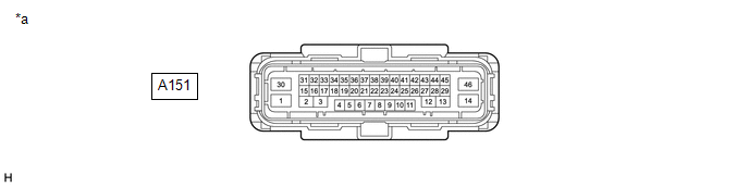
Front view of wire harness connector (to Skid Control ECU (Brake Actuator Assembly)) |
- |
- |
(a) Disconnect the A151 skid control ECU (brake actuator assembly) connector.
(b) Measure the voltage and resistance according to the value (s) in the table below.
|
Terminal No. (Symbol) |
Terminal Description |
Condition |
Specified Condition |
|---|---|---|---|
|
A151-30 (+BS) - Body ground |
Parking brake motor power supply |
Always |
11 to 14 V |
|
A151-36 (IGR) - Body ground |
IG power supply |
Ignition switch ON |
10.5 to 16 V |
|
A151-46 (GND1) - Body ground |
Ground |
1 minute or more after disconnecting the cable from the negative (-) auxiliary battery terminal |
Below 1 Ω |
|
A151-14 (GND2) - Body ground |
Ground |
1 minute or more after disconnecting the cable from the negative (-) auxiliary battery terminal |
Below 1 Ω |
|
A151-2 (MRR+) - Body ground |
Parking brake motor RH (parking brake actuator assembly RH) (+) |
- |
- |
|
A151-3 (MRR-) - Body ground |
Parking brake motor RH (parking brake actuator assembly RH) (-) |
- |
- |
|
A151-13 (MRL+) - Body ground |
Parking brake motor LH (parking brake actuator assembly LH) (+) |
- |
- |
|
A151-12 (MRL-) - Body ground |
Parking brake motor LH (parking brake actuator assembly LH) (-) |
- |
- |
|
A151-18 (POL) - Body ground |
Electric parking brake switch indicator light |
- |
- |
|
A151-31 (SWI1) - Body ground |
Electric parking brake switch (electric parking brake switch assembly) |
- |
- |
|
A151-32 (SWO1) - Body ground |
Electric parking brake switch (electric parking brake switch assembly) |
- |
- |
|
A151-15 (SWI2) - Body ground |
Electric parking brake switch (electric parking brake switch assembly) |
- |
- |
|
A151-16 (SWO2) - Body ground |
Electric parking brake switch (electric parking brake switch assembly) |
- |
- |
|
A151-5 (CANH) - Body ground |
CAN communication line H |
- |
- |
|
A151-19 (CANL) - Body ground |
CAN communication line L |
- |
- |
|
A151-11 (CA2H) |
CAN communication line 2 (H) |
- |
- |
|
A151-25 (CA2L) |
CAN communication line 2 (L) |
- |
- |


