Toyota Corolla Cross: Terminals Of Ecu
TERMINALS OF ECU
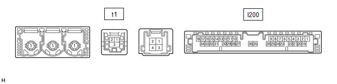
DCM (TELEMATICS TRANSCEIVER)
|
Terminal No. (Symbol) |
Terminal Description |
Condition |
Specified Condition |
|---|---|---|---|
|
I200-1 (+B) - I200-20 (E) |
Power source (+B) |
Ignition switch off |
11 to 14 V |
|
I200-15 (USBV) - I200-20 (E) |
DCM (telematics transceiver) power supply signal |
Ignition switch ON |
4.75 to 5.25 V |
|
Ignition switch off |
Below 1 V |
||
|
I200-17 (VOT+) - I200-20 (E) |
Sent voice signal |
Calling while using the operator service |
A waveform synchronized with the received voice is output |
|
I200-19 (IG2) - I200-20 (E) |
Power source (IG) |
Ignition switch ON |
11 to 14 V |
|
Ignition switch off |
Below 1 V |
||
|
I200-20 (E) - Body ground |
Ground |
Always |
Below 1 Ω |
|
I200-25 (CANP) |
CAN communication signal |
- |
- |
|
I200-26 (CANN) |
CAN communication signal |
- |
- |
|
I200-31 (USBG) - Body ground |
Shield ground |
Always |
Below 1 Ω |
|
I200-33 (VOT-) - I200-20 (E) |
Sent voice signal |
Calling while using the operator service |
A waveform synchronized with the received voice is output |
|
t1-1 (USB-) |
USB communication line |
- |
- |
|
t1-2 (USB+) |
USB communication line |
- |
- |
|
t1-3 (USBS) - Body ground |
Shield ground |
Always |
Below 1 Ω |
CERTIFICATION ECU (SMART KEY ECU ASSEMBLY)
- for HEV Model:
Click here
.gif)
- for Gasoline Model:
Click here


