Toyota Corolla Cross: Terminals Of Ecu
TERMINALS OF ECU
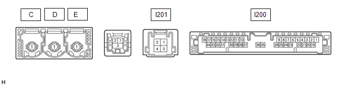
CHECK DCM (TELEMATICS TRANSCEIVER)
|
Terminal No. (Symbol) |
Terminal Description |
Condition |
Specified Condition |
|---|---|---|---|
|
I200-1 (+B) - I200-20 (E) |
Power source (+B) |
Ignition switch off |
11 to 14 V |
|
I200-3 (SIG-) - I200-20 (E) |
Ground |
Always |
Below 1 V |
|
I200-4 (IND1) - I200-20 (E) |
Manual (SOS) switch red indicator illumination signal |
For 2 seconds after turning the ignition switch to ON |
1 to 8.5 V |
|
Ignition switch off |
Below 1 V |
||
|
I200-5 (MCVD) - I200-20 (E) |
Telephone microphone assembly LH power supply |
Ignition switch ON |
7.5 to 8.5 V |
|
Ignition switch off |
Below 1 V |
||
|
I200-6 (MCI+) - I200-20 (E) |
Receive microphone voice signal |
Voice being input to telephone microphone assembly LH |
A waveform synchronized with microphone voice signal is input |
|
I200-7 (MCI-) - I200-20 (E) |
Receive microphone voice signal |
Always |
Below 1 V |
|
I200-13 (GSW) - I200-20 (E) |
Collision detection signal |
Ignition switch ON |
Pulse generation (Refer to waveform 1) |
|
I200-14 (MUTE) - I200-20 (E) |
MUTE Signal |
Audio system playing |
3.5 V or higher |
|
Emergency call mode |
Below 1 V |
||
|
I200-15 (USBV) - I200-20 (E) |
DCM (telematics transceiver) power supply signal |
Ignition switch ON |
4.75 to 5.25 V |
|
Ignition switch off |
Below 1 V |
||
|
I200-16 (MCO+) - I200-20 (E) |
Microphone voice signal |
Voice being input to telephone microphone assembly LH |
A waveform synchronized with microphone voice signal is input |
|
I200-17 (VOT+) - I200-20 (E) |
Sent voice signal |
Calling while using the operator service |
A waveform synchronized with the received voice is output |
|
I200-19 (IG2) - I200-20 (E) |
Power source (IG) |
Ignition switch ON |
11 to 14 V |
|
Ignition switch off |
Below 1 V |
||
|
I200-20 (E) - Body ground |
Ground |
Always |
Below 1 Ω |
|
I200-21 (SIG1) - I200-3 (SIG-) |
Manual (SOS) switch button condition signal |
Manual (SOS) switch not pressed |
1.3 to 1.9 V |
|
Manual (SOS) switch pressed |
0.5 to 0.8 V |
||
|
I200-22 (IND2) - I200-20 (E) |
Manual (SOS) switch green indicator illumination signal |
For 2 seconds after turning the ignition switch to ON |
1 to 8.5 V |
|
Ignition switch off |
Below 1 V |
||
|
I200-23 (SGND) - I200-20 (E) |
Shield ground |
Always |
Below 1 Ω |
|
I200-25 (CANP) |
CAN communication signal |
- |
- |
|
I200-26 (CANN) |
CAN communication signal |
- |
- |
|
I200-31 (USBG) - Body ground |
Shield ground |
Always |
Below 1 Ω |
|
I200-32 (MCO-) - I200-20 (E) |
Microphone voice signal |
Always |
Below 1 V |
|
I200-33 (VOT-) - I200-20 (E) |
Sent voice signal |
Calling while using the operator service |
A waveform synchronized with the received voice is output |
|
I201-1 (SPI+) - I200-20 (E) |
Sound signal |
Audio system playing |
A waveform synchronized with sound signals is output |
|
I201-2 (SPI-) - I200-20 (E) |
Sound signal |
Audio system playing |
A waveform synchronized with sound signals is output |
|
I201-3 (SPO+) - I200-20 (E) |
Sound signal |
Audio system playing, or emergency call mode |
A waveform synchronized with sound signals is output |
|
I201-4 (SPO-) - I200-20 (E) |
Sound signal |
Audio system playing, or emergency call mode |
A waveform synchronized with sound signals is output |
- #: There is no wire color information
(a) Oscilloscope waveform:

(1) Waveform 1
|
Item |
Condition |
|---|---|
|
Tester connection |
I200-13 (GSW) - I200-20 (E) |
|
Tool setting |
5.0 V/DIV., 20 ms./DIV. |
|
Vehicle condition |
Ignition switch ON |
CHECK STEREO COMPONENT AMPLIFIER ASSEMBLY (for 9 Speakers)
Click here .gif)
CHECK RADIO AND DISPLAY RECEIVER ASSEMBLY
Click here


