Toyota Corolla Cross: System Diagram
SYSTEM DIAGRAM
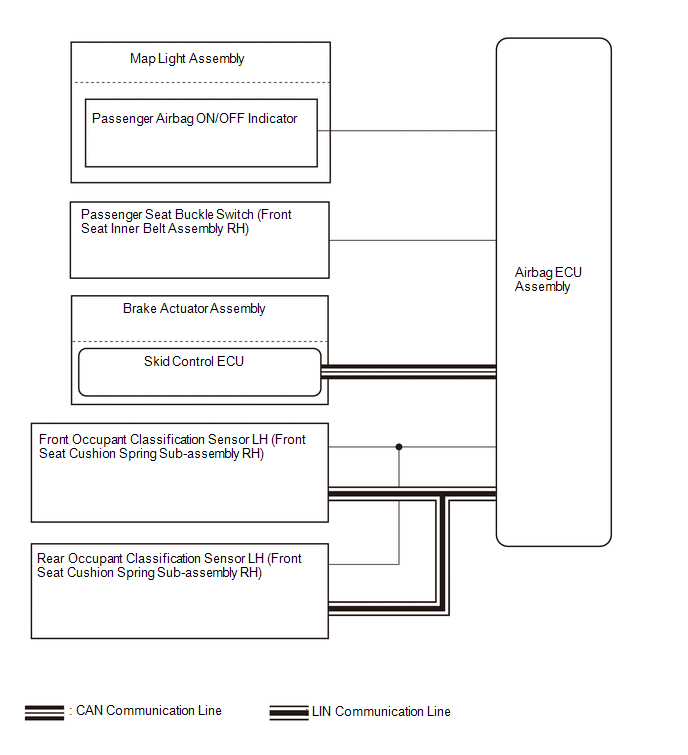
Communication Table
|
Transmitting ECU / Parts (Transmitter) |
Receiving ECU (Receiver) |
Signal | Communication Method |
|
Passenger Seat Buckle Switch (Front Seat Inner Belt Assembly RH) |
Airbag ECU Assembly | Front passenger side buckle switch signal |
Direct line |
|
Passenger Airbag ON/OFF Indicator (Map Light Assembly) |
Airbag ECU Assembly |
- Passenger airbag indicator ON signal
- Passenger airbag indicator OFF signal
|
| Front Occupant Classification Sensor LH (Front Seat Cushion Spring Sub-assembly RH) |
Airbag ECU Assembly |
Occupant load for front passenger signal |
LIN |
| Rear Occupant Classification Sensor LH (Front Seat Cushion Spring Sub-assembly RH) |
Airbag ECU Assembly |
|
Skid Control ECU (Brake Actuator Assembly) |
Airbag ECU Assembly |
- Vehicle speed signal
- Acceleration signal
| CAN |
READ NEXT:
SYSTEM DESCRIPTION GENERAL (a) The airbag ECU assembly estimates the weight of an occupant based on signals received from the 2 occupant classification sensors. The airbag ECU assembly determines whet
CAUTION / NOTICE / HINT
HINT:
Use the following procedure to troubleshoot the occupant classification system.
*: Use the GTS.
PROCEDURE
1. VEHICLE BROUGHT TO WORKSHOP
OPERATION CHECK CHECK SRS WARNING LIGHT (a) Primary check
(1) Turn the ignition switch to ON and check that the SRS warning light turns on.
(2) Turn the ignition switch off. Wait for at least 2 s
SEE MORE:
RemovalREMOVAL CAUTION / NOTICE / HINT COMPONENTS (REMOVAL)
Procedure Part Name Code
1 NO. 2 CONSOLE UPPER PANEL GARNISH
58834B -
- -
2 NO. 1 CONSOLE UPPER PANEL GARNISH
58833B -
- -
3 MOBILE WIRELESS CHARGER
DESCRIPTION Refer to DTC P010511. Click here
DTC No. Detection Item
DTC Detection Condition Trouble Area
MIL Note
P010515 Manifold Absolute Pressure / Barometric Pressure Sensor Circuit Short to Battery or Open
The E.F.I. vacuum sensor assembly output voltag


