Toyota Corolla Cross: System Diagram
SYSTEM DIAGRAM
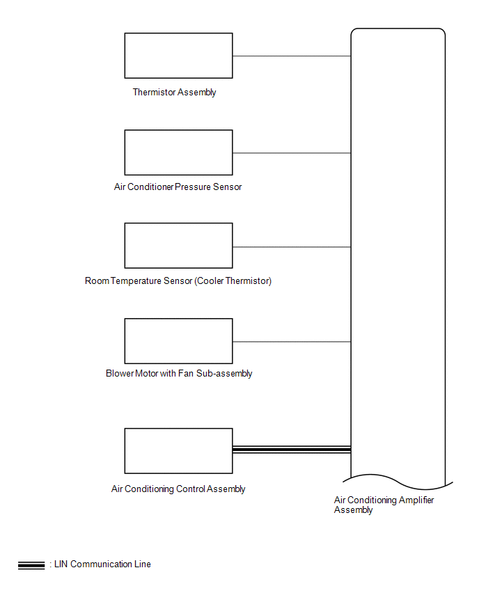
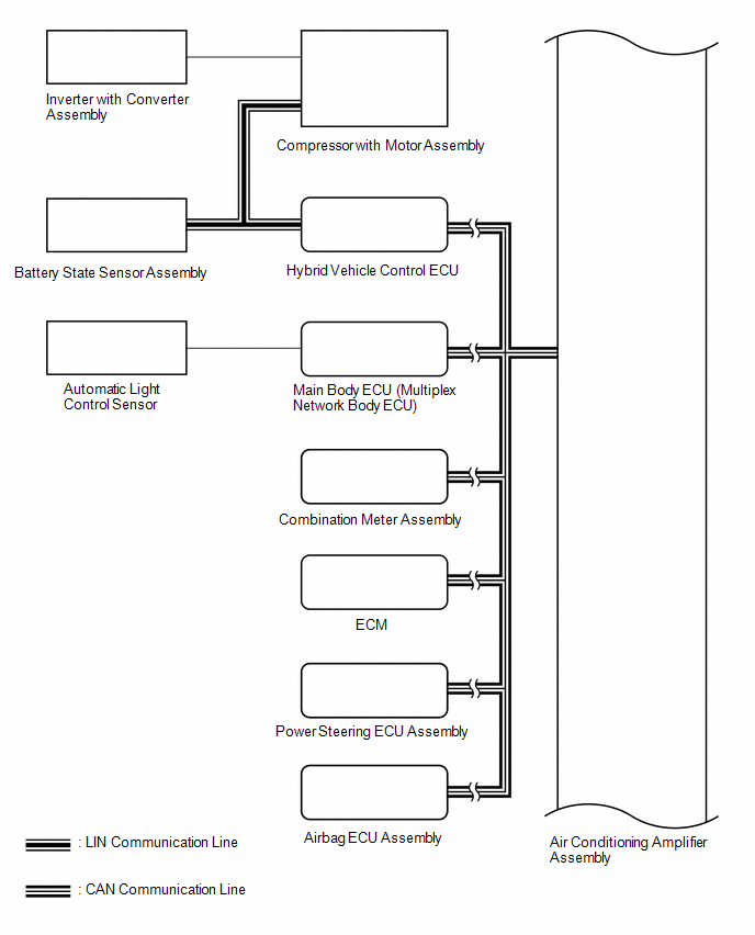
.png)
READ NEXT:
CAUTION / NOTICE / HINT
HINT:
Use the following procedure to troubleshoot the air conditioning system.
*: Use the GTS.
PROCEDURE
1. VEHICLE BROUGHT TO WORKSHOP
CUSTOMIZE PARAMETERS CUSTOMIZE AIR CONDITIONING SYSTEM
(a) Customizing with the GTS.
NOTICE:
When the customer requests a change in a function, first make sure that the function can be customi
INITIALIZATION SERVO MOTOR INITIALIZATION (a) Press the OFF switch.
(b) According to the GTS display, perform servo motor initialization. Body Electrical > Air Conditioner > Utility
Te
SEE MORE:
DTC SUMMARY MALFUNCTION DESCRIPTION This DTC indicates that current does not flow as commanded due to a generator output circuit malfunction. The cause of this malfunction may be one of the following:
Area Main Malfunction Description
Inside of inverter
Inverter with convert
REMOVAL
CAUTION / NOTICE / HINT
COMPONENTS (REMOVAL)
Procedure
Part Name Code
1
REAR WHEELS
-
-
-
-
2
REAR STABILIZER BAR
48812
 How To Proceed With Troubleshooting
 Hybrid/EV Generator Circuit Current Out of Range (P1CA51D)
