Toyota Corolla Cross: System Diagram
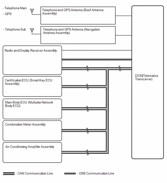
SYSTEM DIAGRAM
READ NEXT:
SYSTEM DESCRIPTION
OUTLINE
(a) Remote Connect, which enables the user to check the vehicle
status and operate the vehicle from a remote location, has been used.
(b) Remote Connect is available by
CAUTION / NOTICE / HINT
HINT:
Use the following procedure to troubleshoot the telematics system.
*: Use the GTS.
PROCEDURE
1.
VEHICLE BROUGHT TO WORKSHOP
OPERATION CHECK
HINT:
This function shows the telematics network status when the DCM (telematics
transceiver) was operated. Use this when no DTC is present but this telematics
system was
SEE MORE:
INSPECTION
PROCEDURE
1. INSPECT TRANSMISSION REVOLUTION SENSOR (NSS)
(a) Connect the battery to the transmission revolution sensor (NSS) as shown
in the illustration.
*1
Battery
*2
Ammeter
*a
Component without harness co
INSTALLATION CAUTION / NOTICE / HINT COMPONENTS (INSTALLATION)
Procedure Part Name Code
1 SIDE TURN SIGNAL LIGHT ASSEMBLY
81740 -
- -
2 OUTER MIRROR LOWER COVER
- -
- -
3 OUTER MIRROR BEZEL
- -
- -
4
 System Description
 Inspection