Toyota Corolla Cross: Servo Motor LIN Communication Bus off (B142A88)
DESCRIPTION
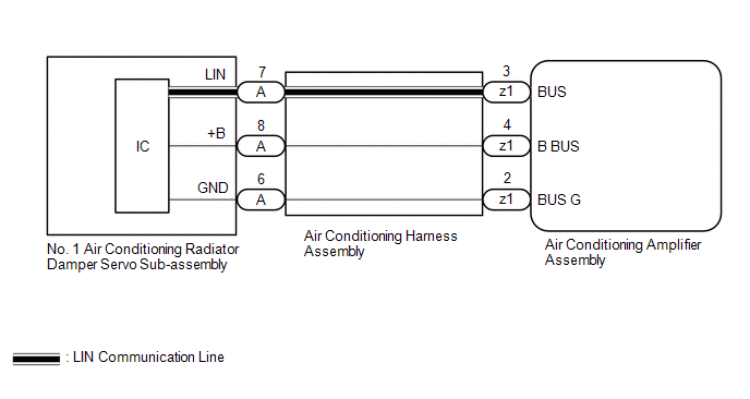
The air conditioning harness assembly connects the air conditioning amplifier assembly and the servo motors. The air conditioning amplifier assembly supplies power and sends operation instructions to each servo motor through the air conditioning harness assembly. Each servo motor sends damper position information to the air conditioning amplifier assembly.
|
DTC No. | Detection Item |
DTC Detection Condition | Trouble Area |
Memory |
|---|---|---|---|---|
| B142A88 |
Servo Motor LIN Communication Bus off |
Diagnosis Condition:
Malfunction Status:
Detection Time:
|
| Memorized |
|
Vehicle Condition | |||
|---|---|---|---|
|
Pattern 1 | Pattern 2 | ||
|
Diagnosis Condition | Ignition switch ON |
○ | ○ |
|
Malfunction | Error communication with each servo motor |
○ | - |
|
Lost communication with each servo motor |
- | ○ | |
|
Detection Time | Continuously for 10 seconds or more |
Continuously for 10 seconds or more | |
|
Trip Count | 1 trip |
1 trip | |
HINT:
If the conditions of either of these patterns are detected, a DTC will be stored
WIRING DIAGRAM
CAUTION / NOTICE / HINT
NOTICE:
This DTC is also output when servomotor initialization has failed. When servomotor initialization has failed, repair any malfunctions and perform servomotor initialization again.
Click here .gif)
PROCEDURE
| 1. |
INSPECT AIR CONDITIONING AMPLIFIER ASSEMBLY |
NOTICE:
When inspecting the air conditioning amplifier assembly, do not bring the tester probes too close to each other as a short circuit may occur.
(a) Disconnect the air conditioning amplifier assembly connector.
| (b) Measure the voltage and resistance according to the value(s) in the table below. Standard Voltage:
Standard Resistance:
|
|
.png)
| NG | .gif) | REPLACE AIR CONDITIONING AMPLIFIER ASSEMBLY |
|
.gif)
| 2. |
INSPECT AIR CONDITIONING AMPLIFIER ASSEMBLY |
.png)
|
*a | Component with harness connected (Air Conditioning Amplifier Assembly) |
(a) Using an oscilloscope, check the waveform.
|
Item | Content |
|---|---|
|
Terminal No. | z1-3 (BUS) - z1-2 (BUS G) |
|
Tool Setting | 2 V/DIV., 2 ms./DIV. |
|
Condition | Ignition switch ON |
OK:
Waveform is similar to that shown in the illustration.
| NG | | REPLACE AIR CONDITIONING AMPLIFIER ASSEMBLY |
|
| 3. |
INSPECT AIR CONDITIONING HARNESS ASSEMBLY |
(a) Disconnect the A No. 1 air conditioning radiator damper servo sub-assembly connector.
(b) Measure the resistance according to the value(s) in the table below.
Standard Resistance:
|
Tester Connection | Condition |
Specified Condition |
|---|---|---|
|
z1-2 (BUS G) - A-6 (GND) |
Always | Below 1 Ω |
|
z1-3 (BUS) - A-7 (LIN) |
Always | Below 1 Ω |
|
z1-4 (B BUS) - A-8 (+B) |
Always | Below 1 Ω |
| OK | | REPLACE NO. 1 AIR CONDITIONING RADIATOR DAMPER SERVO SUB-ASSEMBLY |
| NG | | REPLACE AIR CONDITIONING HARNESS ASSEMBLY |


