Toyota Corolla Cross: Road Test
ROAD TEST
PROBLEM SYMPTOM CONFIRMATION
(a) Based on the result of the customer problem analysis, try to reproduce the symptoms. If the problem is that the transaxle does not change gear ratios or changes ratios at the wrong engine speed, conduct the following road test while referring to the speed variation chart and attempt to duplicate the problem symptoms.
ROAD TEST
CAUTION:
- Strictly observe posted speed limits, traffic laws and road conditions.

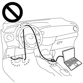
- Do not drive the vehicle with the cable of the GTS contacting the pedals, shift lever or steering wheel.
- Driving the vehicle with the cable of the GTS contacting these areas could impede vehicle control, resulting in a serious accident.
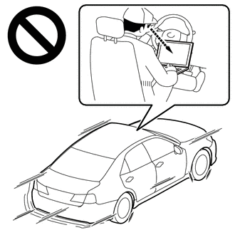
- Do not operate the GTS while driving the vehicle.

- Operating the GTS while driving the vehicle will prevent you from paying sufficient attention to vehicle surroundings, and could result in a serious accident.
NOTICE:
- This test must be performed after checking and confirming that the engine is normal.
- Perform this test with the CVT fluid temperature between 50 and 100°C (122 and 212°F).
- Perform this test with the air conditioning off.
HINT:
- Lock-up control will not operate when the CVT fluid temperature is 20°C (68°F) or less and the vehicle speed is 60 km/h (37 mph) or less, or when the CVT fluid temperature is 5°C (41°F) or less.
- Lock-up control will not operate when the engine coolant temperature is 20°C (68°F) or less.
- The lock-up OFF vehicle speed may vary depending on electrical load, and air conditioning and brake operation.
- Keep a constant accelerator pedal opening angle to maintain the specified vehicle speed.
- When fully depressing the accelerator pedal, read the engine speed immediately after the pedal is fully depressed.
Speed Variation Chart:
|
Shift Lever Position |
Accelerator Pedal Position (Vehicle Speed) |
|||||
|---|---|---|---|---|---|---|
|
Fully Depressed (Before 1st up-shift) *1 |
Fully Depressed (Before 2nd up-shift) *2 |
Constant Position (30 km/h (19 mph)) *5 |
Constant Position (70 km/h (43 mph)) *4 |
Constant Position (100 km/h (62 mph)) *3 |
Fully Depressed (Accelerating from 30 km/h (19 mph)) *6 |
|
|
D |
6100 to 6900 rpm |
6100 to 6900 rpm |
750 to 1200 rpm |
1000 to 1500 rpm |
1300 to 1800 rpm |
2500 rpm or more |
Lock-up Schedule:
|
Shift Lever Position |
Lock-up Condition (Accelerator Pedal Opening Angle) |
|
|---|---|---|
|
Lock-up ON (5%) |
Lock-up OFF (0%) |
|
|
D |
10 to 30 km/h (6 to 19 mph) |
5 to 20 km/h (3 to 12 mph) |
(a) D position test
Move the shift lever to D and check the following:
(1) Check if the gear ratio changes during normal driving (average urban driving).
- With the vehicle stopped, fully depress the accelerator pedal and check the engine speed at the shift timing listed in *1 and *2 in the speed variation chart.
- With the vehicle stopped, depress the accelerator pedal to a constant intermediate position and check the engine speed when the vehicle reaches the vehicle speed listed in *3 in the speed variation chart.
- Release the accelerator pedal and check the engine speed when the vehicle decelerates to the vehicle speed listed in *4 in the speed variation chart.
- Release the accelerator pedal and check the engine speed when the vehicle decelerates to the vehicle speed listed in *5 in the speed variation chart.
- Fully depress the accelerator pedal and check the engine speed as the vehicle accelerates from the vehicle speed listed in *6 in the speed variation chart.
(2) Check for abnormal noises and vibration.
HINT:
Inspections for the cause of abnormal noise and vibration must be done thoroughly as they could also be due to loss of balance in the differential, torque converter clutch, etc.
(3) Check for abnormal shock and slippage at kick-down.
(4) Check the lock-up mechanism.
(b) M position test
Move the shift lever to M and check the following:
(1) Check the shift operation.
- When driving with M10 selected (vehicle speed approximately 95 to 100 km/h (59 to 62 mph)), check the engine braking effect in M9 when the shift lever is moved to "-".
- When driving with M9 selected (vehicle speed approximately 90 to 95 km/h (56 to 59 mph)), check the engine braking effect in M8 when the shift lever is moved to "-".
- When driving with M8 selected (vehicle speed approximately 80 to 90 km/h (50 to 56 mph)), check the engine braking effect in M7 when the shift lever is moved to "-".
- When driving with M7 selected (vehicle speed approximately 70 to 80 km/h (43 to 50 mph)), check the engine braking effect in M6 when the shift lever is moved to "-".
- When driving with M6 selected (vehicle speed approximately 60 to 70 km/h (37 to 43 mph)), check the engine braking effect in M5 when the shift lever is moved to "-".
- When driving with M5 selected (vehicle speed approximately 50 to 60 km/h (31 to 37 mph)), check the engine braking effect in M4 when the shift lever is moved to "-".
- When driving with M4 selected (vehicle speed approximately 40 to 50 km/h (25 to 31 mph)), check the engine braking effect in M3 when the shift lever is moved to "-".
- When driving with M3 selected (vehicle speed approximately 30 to 40 km/h (19 to 25 mph)), check the engine braking effect in M2 when the shift lever is moved to "-".
- When driving with M2 selected (vehicle speed approximately 20 to 30 km/h (12 to 19 mph)), check the engine braking effect in M1 when the shift lever is moved to "-".
(c) R position test
Move the shift lever to R and lightly depress the accelerator pedal. Check that the vehicle moves backward without any abnormal noise or vibration.
CAUTION:
Before conducting this test, make sure that the test area is free from people and obstructions.
(d) P position test
Stop the vehicle on an incline (approximately 5° or more). Move the shift lever to P and release the parking brake. Check that the parking lock pawl holds the vehicle in place.


