Toyota Corolla Cross: Removal
REMOVAL
CAUTION / NOTICE / HINT
COMPONENTS (REMOVAL)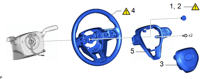
|
Procedure |
Part Name Code |
.png) |
.png) |
.png) |
|
|---|---|---|---|---|---|
|
1 |
PRECAUTION |
- |
|
- |
- |
|
2 |
ALIGN FRONT WHEELS FACING STRAIGHT AHEAD |
- |
|
- |
- |
|
3 |
HORN BUTTON ASSEMBLY |
45130 |
- |
- |
- |
|
4 |
STEERING WHEEL ASSEMBLY |
45100 |
|
- |
- |
|
5 |
STEERING PAD SWITCH ASSEMBLY |
84250A |
- |
- |
- |
|
Procedure |
Part Name Code |
|
|
|
|
|---|---|---|---|---|---|
|
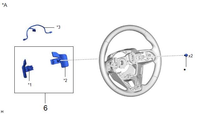
6 |
SHIFT PADDLE SWITCH (TRANSMISSION SHIFT SWITCH ASSEMBLY) |
- |
- |
- |
- |
|
*A |
w/ Shift Paddle Switch |
- |
- |
|
*1 |
NO. 1 TRANSMISSION SHIFT SWITCH ASSEMBLY |
*2 |
NO. 2 TRANSMISSION SHIFT SWITCH ASSEMBLY |
|
*3 |
NO. 1 SWITCH WIRE |
- |
- |
|
● |
Non-reusable part |
★ |
Precoated part |
CAUTION / NOTICE / HINT
NOTICE:
- Do not remove/install the spiral cable with sensor sub-assembly with the auxiliary battery connected and the ignition switch (for Gasoline Model) or power switch (for HV Model) on (IG).
- Do not rotate the spiral cable with sensor sub-assembly without the steering wheel assembly installed, with the auxiliary battery connected and the ignition switch (for Gasoline Model) or power switch (for HV Model) on (IG).
- Ensure that the steering wheel assembly is installed and aligned straight when inspecting the steering sensor.
- After the ignition switch is turned off, the navigation system records various types of memory and settings. As a result, after turning the ignition switch off, make sure to wait at least 3 minutes before disconnecting the cable from the negative (-) battery terminal.
- When the cable is disconnected from the negative (-) auxiliary battery terminal and the security lock setting has been enabled, multi-display operations will be disabled upon next startup unless the password is entered. Be sure to check the security lock setting before disconnecting the cable from the negative (-) auxiliary battery terminal.
HINT:
When the cable is disconnected/reconnected to the auxiliary battery terminal, systems temporarily stop operating. However, each system has a function that completes learning the first time the system is used.
for HEV Model:- Learning completes when vehicle is driven
Effect/Inoperative Function When Necessary Procedures are not Performed
Necessary Procedures
Link
Front camera system
Drive the vehicle straight ahead at 15 km/h (10 mph) or more for 1 second or more.
.gif)
- Learning completes when vehicle is operated normally
Effect/Inoperative Function When Necessary Procedures are not Performed
Necessary Procedures
Link
Power door lock control system
- Back door opener
Perform door unlock operation with door control switch or electrical key transmitter sub-assembly switch.
Power back door system
Fully close the back door by hand.
HINT:
Initialization is not necessary if the above procedures are performed while the back door is closed.
Air conditioning system
After the ignition switch is turned to ON, the servo motor standard position is recognized.
-
- Learning completes when vehicle is driven
Effect/Inoperative Function When Necessary Procedures are not Performed
Necessary Procedures
Link
Front camera system
Drive the vehicle straight ahead at 15 km/h (10 mph) or more for 1 second or more.
Stop and start system
Drive the vehicle until stop and start control is permitted (approximately 5 to 60 minutes)
- Learning completes when vehicle is operated normally
Effect/Inoperative Function When Necessary Procedures are not Performed
Necessary Procedures
Link
Power door lock control system
- Back door opener
Perform door unlock operation with door control switch or electrical key transmitter sub-assembly switch.
Power back door system
Fully close the back door by hand.
HINT:
Initialization is not necessary if the above procedures are performed while the back door is closed.
Air conditioning system
After the ignition switch is turned to ON, the servo motor standard position is recognized.
-
PROCEDURE
1. PRECAUTION
|
|
Click here |
2. ALIGN FRONT WHEELS FACING STRAIGHT AHEAD
|
|
Click here |
3. REMOVE HORN BUTTON ASSEMBLY
Click here
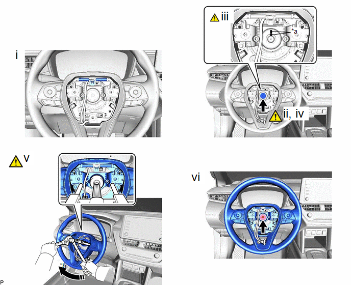
4. REMOVE STEERING WHEEL ASSEMBLY
|
*a |
Matchmark |
*b |
Hold |
.png) |
Turn |
- |
- |
(1) Disconnect each connector.
HINT:
As the illustration shown is an example, the actual details may differ.
(2) Using a 10 mm hexagon socket wrench, remove the steering wheel assembly set bolt.
(3) Put matchmarks on the steering wheel assembly and steering main shaft.
(4) Temporarily install the steering wheel assembly set bolt.
NOTICE:
Do not overtighten the steering wheel assembly set bolt.
(5) Using SST, separate the steering wheel assembly.
SST: 09950-50013
09951-05010
09952-05010
09953-05020
09954-05031
09957-04010
SST: 09950-60011
09951-00330
NOTICE:
Apply a small amount of grease to the threads and tip of SST (09953-05020) before use.
(6) Remove the steering wheel assembly set bolt and steering wheel assembly.
5. REMOVE STEERING PAD SWITCH ASSEMBLY
Click here
6. REMOVE SHIFT PADDLE SWITCH (TRANSMISSION SHIFT SWITCH ASSEMBLY) (w/ Shift Paddle Switch)
Click here


