Toyota Corolla Cross: Removal
REMOVAL
CAUTION / NOTICE / HINT
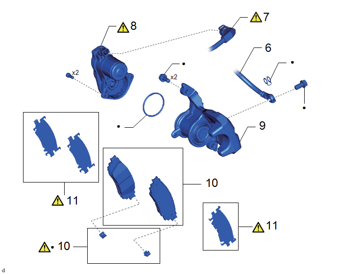
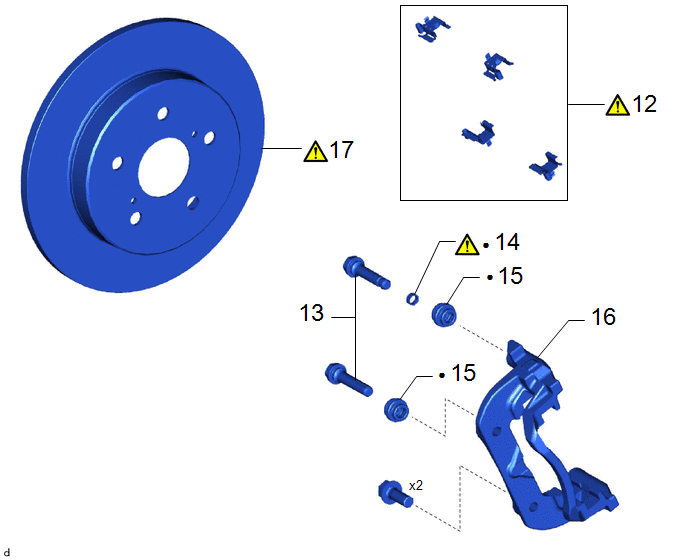
COMPONENTS (REMOVAL)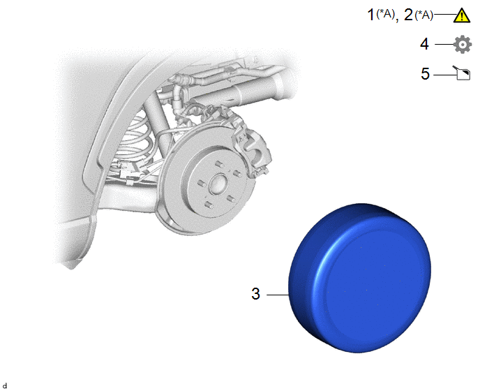
|
Procedure |
Part Name Code |
.png) |
.png) |
.png) |
|
|---|---|---|---|---|---|
|
1 |
PRECAUTION |
- |
|
- |
- |
|
2 |
DISCONNECT CABLE FROM NEGATIVE AUXILIARY BATTERY TERMINAL |
- |
|
- |
- |
|
3 |
REAR WHEEL |
- |
- |
- |
- |
|
4 |
REAR BRAKE PAD REPLACEMENT MODE |
- |
- |
- |
|
|
5 |
DRAIN BRAKE FLUID |
- |
- |
|
- |
|
*A |
for HEV Model |
- |
- |
|
Procedure |
Part Name Code |
|
|
|
|
|---|---|---|---|---|---|
|
6 |
REAR FLEXIBLE HOSE |
47319F |
- |
- |
- |
|
7 |
NO. 2 PARKING BRAKE WIRE ASSEMBLY |
89C0A |
|
- |
- |
|
8 |
PARKING BRAKE ACTUATOR ASSEMBLY |
46310B |
|
- |
- |
|
9 |
DISC BRAKE CYLINDER ASSEMBLY |
- |
- |
- |
- |
|
10 |
REAR DICSC BRAKE PAD KIT |
04466 |
- |
- |
- |
|
11 |
REAR DISC BRAKE ANTI-SQUEAL SHIM KIT |
- |
|
- |
- |
|
● |
Non-reusable part |
- |
- |
|
Procedure |
Part Name Code |
|
|
|
|
|---|---|---|---|---|---|
|
12 |
REAR DISC BRAKE PAD SUPPORT PLATE |
04946 |
|
- |
- |
|
13 |
REAR DISC BRAKE CYLINDER SLIDE PIN |
- |
- |
- |
- |
|
14 |
REAR DISC BRAKE CYLINDER SLIDE BUSH |
- |
|
- |
- |
|
15 |
REAR DISC BRAKE BUSHING DUST BOOT |
- |
- |
- |
- |
|
16 |
REAR DISC BRAKE CYLINDER MOUNTING |
- |
- |
- |
- |
|
17 |
REAR DISC |
42431 |
|
- |
- |
|
● |
Non-reusable part |
- |
- |
CAUTION / NOTICE / HINT
for HEV Model:HINT:
When the cable is disconnected/reconnected to the auxiliary battery terminal, systems temporarily stop operating. However, each system has a function that completes learning the first time the system is used.
- Learning completes when vehicle is driven
Effect/Inoperative Function When Necessary Procedures are not Performed
Necessary Procedures
Link
Front Camera System
Drive the vehicle straight ahead at 15 km/h (10 mph) or more for 5 second or more.
.gif)
- Learning completes when vehicle is operated normally
Effect/Inoperative Function When Necessary Procedures are not Performed
Necessary Procedures
Link
Power door lock control system
- Back door opener
Perform door unlock operation with door control switch or electrical key transmitter sub-assembly switch.
Power back door system
Fully close the back door by hand.
HINT:
Initialization is not necessary if the above procedures are performed while the back door is closed.
Air conditioning system
After the ignition switch is turned to ON, the servo motor standard position is recognized.
-
CAUTION / NOTICE / HINT
The necessary procedures (adjustment, calibration, initialization, or registration) that must be performed after parts are removed and installed, or replaced during the rear brake removal/installation are shown below.
NOTICE:
- Immediately after installing the rear disc brake pads, the braking performance may be reduced. Always perform a road test in a safe place while paying attention to the surroundings.
- After replacing the rear disc brake pads, the brake pedal may feel soft due to clearance between the rear disc brake pads and rear disc. Depress the brake pedal several times until the brake pedal feels firm.
- After replacing the rear disc brake pads, always perform a road test to check the braking performance and check for vibrations.
- When removing or installing the rear disc brake cylinder assembly, pushing back the disc brake piston may cause a large clearance between the brake pads and brake disc. When the brake pedal is depressed with a large clearance between the brake pads and the brake disc, DTCs related to abnormal brake fluid pressure may be stored.Make sure to clear any DTCs after performing this procedure. (for HEV Model)
- While the auxiliary battery is connected, even if the ignition switch is off, the brake control system activates when the brake pedal is depressed or any door courtesy switch turns on. Therefore, when servicing the brake system components, do not operate the brake pedal or open/close the doors while the auxiliary battery is connected. (for HEV Model)
HINT:
- Use the same procedure for the RH side and LH side.
- The following procedure is for the LH side.
PROCEDURE
1. PRECAUTION (for HEV Model)
|
|
NOTICE: Make sure to read the precautions of the electric parking brake system before removing the rear brake assembly. Click here |
2. DISCONNECT CABLE FROM NEGATIVE AUXILIARY BATTERY TERMINAL (for HEV Model)
Click here
3. REMOVE REAR WHEEL
Click here
4. PERFORM REAR BRAKE PAD REPLACEMENT MODE
- for HEV model:
Click here
- for Gasoline model:
Click here
5. DRAIN BRAKE FLUID
|
|
NOTICE: If brake fluid leaks onto any painted surface, immediately wash it off. |
6. DISCONNECT REAR FLEXIBLE HOSE

7. DISCONNECT NO. 2 PARKING BRAKE WIRE ASSEMBLY
|
|
Click here |
8. REMOVE PARKING BRAKE ACTUATOR ASSEMBLY
|
|
Click here |
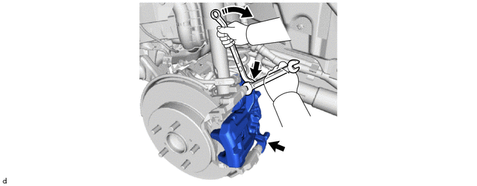
9. REMOVE DISC BRAKE CYLINDER ASSEMBLY
10. REMOVE REAR DICSC BRAKE PAD KIT

11. REMOVE REAR DISC BRAKE ANTI-SQUEAL SHIM KIT
|
|
Click here |
12. REMOVE REAR DISC BRAKE PAD SUPPORT PLATE
|
|
NOTICE: Each rear disc brake pad support plate has a different shape. Be sure to put an identification mark on each rear disc brake pad support plate so that it can be reinstalled to its original position. |

13. REMOVE REAR DISC BRAKE CYLINDER SLIDE PIN

|
*1 |
Rear No. 1 Disc Brake Cylinder Slide Pin |
*2 |
Rear No. 2 Disc Brake Cylinder Slide Pin |
14. REMOVE REAR DISC BRAKE CYLINDER SLIDE BUSH

(1) Using a screwdriver with its tip wrapped with protective tape, remove the rear disc brake cylinder slide bushing from the rear No. 2 disc brake cylinder slide pin.
NOTICE:
Do not damage the rear No. 2 disc brake cylinder slide pin.
15. REMOVE REAR DISC BRAKE BUSHING DUST BOOT

16. REMOVE REAR DISC BRAKE CYLINDER MOUNTING

17. REMOVE REAR DISC

|
*a |
Matchmark |
- |
- |
(1) Put matchmarks on the rear disc and rear axle hub and bearing assembly.
(2) Remove the rear disc.


