Toyota Corolla Cross: Removal
REMOVAL
CAUTION / NOTICE / HINT
COMPONENTS (REMOVAL)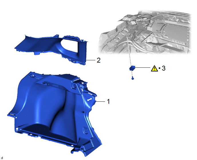
|
Procedure |
Part Name Code |
.png) |
.png) |
.png) |
|
|---|---|---|---|---|---|
|
1 |
DECK TRIM SIDE PANEL ASSEMBLY LH |
64740C |
- |
- |
- |
|
2 |
ROOF SIDE INNER GARNISH ASSEMBLY LH |
62480A |
- |
- |
- |
|
3 |
RADIO SETTING CONDENSER |
86011A |
|
- |
- |
|
● |
Non-reusable part |
- |
- |
PROCEDURE
1. REMOVE DECK TRIM SIDE PANEL ASSEMBLY LH
Click here .gif)
2. REMOVE ROOF SIDE INNER GARNISH ASSEMBLY LH
Click here
3. REMOVE RADIO SETTING CONDENSER
|
|
NOTICE: When a terminal cover is removed, the radio setting condenser must be replaced because the terminal covers and condenser are supplied as a set. |

(1) Remove the bolt.
(2) Disengage the clamp to disconnect the radio setting condenser with wire harness from the vehicle body.
|
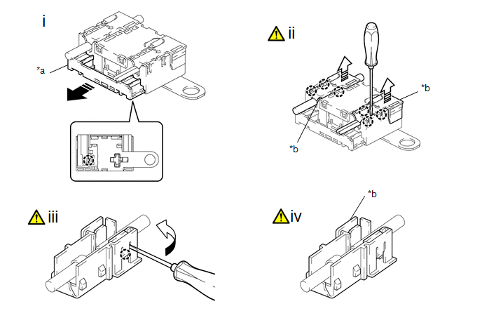
*a |
Cover |
*b |
Terminal Cover |
.png) |
Pull in this Direction |
.png) |
Remove in this Direction |
(1) Disengage the claw to pull out the cover as shown in the illustration.
(2) Using a screwdriver, disengage the claws to remove the 2 terminal covers with wire harness from the radio setting condenser as shown in the illustration.
(3) Using a screwdriver, bend back and break off the claw as shown in the illustration.
HINT:
Use the same procedure for the other terminal cover.
(4) Remove the terminal cover from the wire harness.
NOTICE:
- Make sure to hold the crimped side of the terminal when disconnecting the wire harness from the terminal cover.
- Make sure not to bend the exposed wire when disconnecting the wire harness from the terminal cover.
- Check for deformation of the terminal after the wire harness has been removed from the terminal cover.
HINT:
Use the same procedure for the other terminal cover.


