Toyota Corolla Cross: Rear Seat Belt Warning Light Malfunction
DESCRIPTION
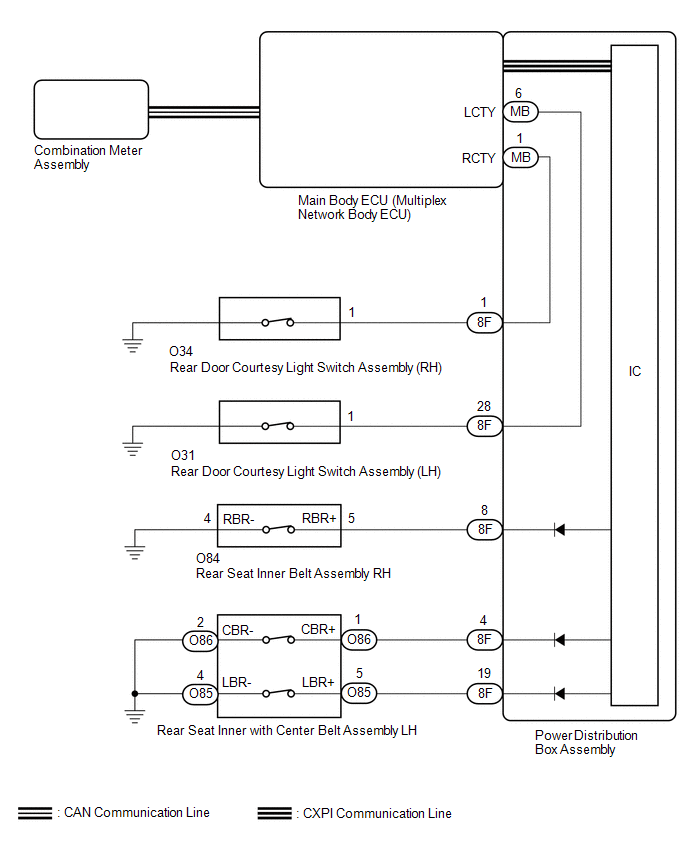
The power distribution box assembly sends a signal indicating a rear seat belt status when the ignition switch is ON to the main body ECU (multiplex network body ECU) via CXPI communication.
The main body ECU (multiplex network body ECU) sends a signal indicating the rear door courtesy light switch status when the ignition switch is ON or off and a signal indicating a rear seat belt status when the ignition switch is ON to the combination meter assembly via CAN communication.
Depending on the rear door courtesy light switch signal, rear seat belt status, shift position and vehicle speed, the combination meter assembly illuminates or turns off the rear seat belt warning light.
WIRING DIAGRAM
CAUTION / NOTICE / HINT
NOTICE:
- The seat belt warning system uses the CAN communication system and CXPI communication system. First, confirm that there is no malfunction in the CAN communication system and CXPI communication system. Refer to the How to Proceed with Troubleshooting procedure.
Click here
.gif)
- Before replacing the main body ECU (multiplex network body ECU), refer to Registration.
- for HEV Model:
Click here
- for Gasoline Model:
Click here
- for HEV Model:
- When replacing the combination meter assembly, always replace it with a new one. If a combination meter assembly which was installed to another vehicle is used, the information stored in it will not match the information from the vehicle and a DTC may be stored.
PROCEDURE
|
1. | READ VALUE USING GTS |
(a) Read the Data List according to the display on the GTS.
Body Electrical > Main Body > Data List|
Tester Display | Measurement Item |
Range | Normal Condition |
Diagnostic Note |
|---|---|---|---|---|
|
RR Door Courtesy Switch Status |
Rear door courtesy light switch (RH) signal |
Close or Open | Close: Rear door RH closed Open: Rear door RH open |
- |
| RL Door Courtesy Switch Status |
Rear door courtesy light switch (LH) signal |
Close or Open | Close: Rear door LH closed Open: Rear door LH open |
- |
|
Tester Display |
|---|
| RR Door Courtesy Switch Status |
|
RL Door Courtesy Switch Status |
OK:
The GTS display changes correctly in response to the rear door courtesy light switch condition.
| NG | .gif) | GO TO LIGHTING SYSTEM (Proceed to Rear Door Courtesy Switch Circuit) |
|
.gif)
| 2. |
READ VALUE USING GTS |
(a) Read the Data List according to the display on the GTS.
Body Electrical > Power Distribution Box > Data List|
Tester Display | Measurement Item |
Range | Normal Condition |
Diagnostic Note |
|---|---|---|---|---|
|
Rear Seat RH Buckle Switch Status |
Rear RH seat belt buckle switch |
Set, Unset or Unknown | Set: Rear RH seat belt buckle switch fastened Unset: Rear RH seat belt buckle switch unfastened Unknown: Data is not determined |
- |
| Rear Seat Center Buckle Switch Status |
Rear center seat belt buckle switch |
Set, Unset or Unknown | Set: Rear center seat belt buckle switch fastened Unset: Rear center seat belt buckle switch unfastened Unknown: Data is not determined |
- |
| Rear Seat LH Buckle Switch Status |
Rear LH seat belt buckle switch |
Set, Unset or Unknown | Set: Rear LH seat belt buckle switch fastened Unset: Rear LH seat belt buckle switch unfastened Unknown: Data is not determined |
- |
|
Tester Display |
|---|
| Rear Seat RH Buckle Switch Status |
|
Rear Seat Center Buckle Switch Status |
|
Rear Seat LH Buckle Switch Status |
OK:
The GTS display changes correctly in response to the rear seat belt buckle switch condition.
|
Result | Proceed to |
|---|---|
|
OK | A |
|
NG (Unknown displayed) |
B |
| NG (Rear RH seat belt malfunction) |
C |
| NG (Rear center seat belt malfunction) |
D |
| NG (Rear LH seat belt malfunction) |
E |
| A |
| REPLACE COMBINATION METER ASSEMBLY |
| B |
| REPLACE POWER DISTRIBUTION BOX ASSEMBLY |
| D |
| GO TO STEP 5 |
| E |
| GO TO STEP 7 |
|
| 3. |
INSPECT REAR SEAT INNER BELT ASSEMBLY RH |
Click here
| NG | | REPLACE REAR SEAT INNER BELT ASSEMBLY RH |
|
| 4. |
CHECK HARNESS AND CONNECTOR (REAR SEAT INNER BELT ASSEMBLY RH - POWER DISTRIBUTION BOX ASSEMBLY AND BODY GROUND) |
(a) Disconnect the 8F power distribution box assembly connector.
(b) Measure the resistance according to the value(s) in the table below.
Standard Resistance:
|
Tester Connection | Condition |
Specified Condition |
|---|---|---|
|
O84-5 (RBR+) - 8F-8 | Always |
Below 1 Ω |
|
O84-5 (RBR+) or 8F-8 - Body ground |
Always | 10 kΩ or higher |
|
O84-4 (RBR-) - Body ground |
Always | Below 1 Ω |
| OK | | REPLACE POWER DISTRIBUTION BOX ASSEMBLY |
| NG | | REPAIR OR REPLACE HARNESS OR CONNECTOR |
| 5. |
INSPECT REAR SEAT INNER WITH CENTER BELT ASSEMBLY LH |
Click here
| NG | | REPLACE REAR SEAT INNER WITH CENTER BELT ASSEMBLY LH |
|
| 6. |
CHECK HARNESS AND CONNECTOR (REAR SEAT INNER WITH CENTER BELT ASSEMBLY LH - POWER DISTRIBUTION BOX ASSEMBLY AND BODY GROUND) |
(a) Disconnect the 8F power distribution box assembly connector.
(b) Measure the resistance according to the value(s) in the table below.
Standard Resistance:
|
Tester Connection | Condition |
Specified Condition |
|---|---|---|
|
O86-1 (CBR+) - 8F-4 | Always |
Below 1 Ω |
|
O86-1 (CBR+) or 8F-4 - Body ground |
Always | 10 kΩ or higher |
|
O86-2 (CBR-) - Body ground |
Always | Below 1 Ω |
| OK | | REPLACE POWER DISTRIBUTION BOX ASSEMBLY |
| NG | | REPAIR OR REPLACE HARNESS OR CONNECTOR |
| 7. |
INSPECT REAR SEAT INNER WITH CENTER BELT ASSEMBLY LH |
Click here
| NG | | REPLACE REAR SEAT INNER WITH CENTER BELT ASSEMBLY LH |
|
| 8. |
CHECK HARNESS AND CONNECTOR (REAR SEAT INNER WITH CENTER BELT ASSEMBLY LH - POWER DISTRIBUTION BOX ASSEMBLY AND BODY GROUND) |
(a) Disconnect the 8F power distribution box assembly connector.
(b) Measure the resistance according to the value(s) in the table below.
Standard Resistance:
|
Tester Connection | Condition |
Specified Condition |
|---|---|---|
|
O85-5 (LBR+) - 8F-19 |
Always | Below 1 Ω |
|
O85-5 (LBR+) or 8F-9 - Body ground |
Always | 10 kΩ or higher |
|
O85-4 (LBR-) - Body ground |
Always | Below 1 Ω |
| OK | | REPLACE POWER DISTRIBUTION BOX ASSEMBLY |
| NG | | REPAIR OR REPLACE HARNESS OR CONNECTOR |


