Toyota Corolla Cross: Pressure Control Solenoid "M" Actuator Stuck Off (P08C37F,P091400)
DESCRIPTION
Using the current from the TCM, the shift solenoid valve SLG controls the B1 brake when the shift lever is in R, and controls the S1 synchronizer when the shift lever is in P, N, D or M.
When the TCM requests the shift mode to be changed to gear mode, the S1 synchronizer is engaged and input torque is transferred to the 1st gear.
When the TCM requests the shift mode to be changed to belt mode and certain conditions are met, the S1 synchronizer is released and input torque is not transferred to the 1st gear.
The shift stroke sensor detects the S1 synchronizer position using the magnet on the shift fork, and sends signals to the TCM.
|
DTC No. |
Detection Item |
DTC Detection Condition |
Trouble Area |
MIL |
Memory |
Note |
|---|---|---|---|---|---|---|
|
P08C37F |
Pressure Control Solenoid "M" Actuator Stuck Off |
Any of the following conditions are met (2-trip detection logic):
|
|
Comes on |
DTC stored |
SAE Code: P08C4 |
|
P091400 |
Gear Shift Position Circuit Range/Performance |
Any of the following conditions are met (2-trip detection logic):
|
|
Comes on |
DTC stored |
SAE Code: P0915 |
MONITOR DESCRIPTION
With the shift lever in P, N, D or M, the shift solenoid valve SLG controls the S1 synchronizer and moves it to the requested position according to the requested shift mode.
When the TCM detects that the S1 synchronizer is not in the appropriate position, it determines that the shift solenoid valve SLG or shift stroke sensor is malfunctioning, illuminates the MIL and stores a DTC.
MONITOR STRATEGY
| *: at CVT fluid temperature 80°C (176°F)
(Conditions vary with CVT fluid temperature) |
|
|
Related DTCs |
P08C4: Pressure control solenoid "M" (Shift solenoid valve SLG)/Functional check P0915: Gear shift position (SFV)/Rationality fault diagnostics |
|
Required sensors/Components |
Crankshaft position sensor Transmission revolution sensor (NC1) Transmission revolution sensor (NOUT) CVT fluid temperature sensor Engine coolant temperature sensor Oil pressure sensor Shift solenoid valve SL1 Shift solenoid valve SL2 Shift solenoid valve SLP Shift solenoid valve SLS Shift solenoid valve SLG |
|
Frequency of operation |
Continuous |
|
Duration |
P08C4:
|
|
MIL operation |
2 driving cycles |
|
Sequence of operation |
None |
TYPICAL ENABLING CONDITIONS
All|
ETC system (Electronic throttle control system) |
Not system down (MIL illuminated by following codes: P0121, P0122, P0123, P0222, P0223, P0604, P0606, P0607, P060D, P060E, P0657, P0658, P1607, P16B0, P2102, P2103, P2111, P2112, P2119, P2135) |
|
KCS sensor circuit (Knock sensor) |
Not circuit malfunction (MIL illuminated by following codes: P0327, P0328) |
|
ECT sensor circuit (Engine coolant temperature sensor) |
Not circuit malfunction (MIL illuminated by following codes: P0117, P0118) |
|
IAT sensor circuit (Intake air temperature sensor) |
Not circuit malfunction (MIL illuminated by following codes: P0112, P0113) |
|
Crankshaft position sensor "A" circuit (Crankshaft position sensor) |
Not circuit malfunction (MIL illuminated by following codes: P0335, P0337, P0338) |
|
CAN communication between ECM and TCM |
Not system down (MIL illuminated by following codes: U0100, U0101) |
|
Low voltage flag |
OFF |
|
Pressure control solenoid "K" circuit (Shift solenoid valve SLS) |
Not circuit malfunction (MIL illuminated by following codes: P282F, P2830) |
|
Pressure Control Solenoid "M" circuit (Shift solenoid valve SLG) |
Not circuit malfunction (MIL illuminated by following codes: P08CA, P08CB) |
|
Transmission fluid temperature sensor "A" circuit (CVT fluid temperature sensor) |
Not circuit malfunction (MIL illuminated by following codes: P0712, P0713) |
|
Turbine speed sensor "A" circuit (Transmission revolution sensor (NT)) |
Not circuit malfunction (MIL illuminated by following codes: P0717, P07BF, P07C0) |
|
Intermediate shaft speed sensor "C" circuit (Transmission revolution sensor (NSS)) |
Not circuit malfunction (MIL illuminated by following codes: P07C9, P07CA, P2751) |
|
Gear shift position circuit |
Not circuit malfunction (MIL illuminated by following codes: P0916, P0917) |
|
Output speed sensor circuit (Transmission revolution sensor (NOUT)) |
Not circuit malfunction (MIL illuminated by following codes: P0722, P077C, P077D) |
|
Intermediate shaft speed sensor "B" circuit (Transmission revolution sensor (NC1)) |
Not circuit malfunction (MIL illuminated by following codes: P07C7, P07C8, P2747) |
- OFF malfunction (A)
OFF malfunction (B)Shift position
"N" or "P" or "D" or "B"
Shift solenoid valve SLP
Operating shift control by TCM command
Engine speed
500 rpm or more
ON malfunction (A)Engine speed
550 rpm or more
Transmission fluid temperature
-10°C (14°F) or more
Time after following condition is met
0.5 sec. or more
- l Variation of the accelerator pedal angle l
(within 32.768 msec.)
Less than 0.5%
Shift solenoid valve SLS
Operating clamping pressure control by TCM command
ECT
60°C (140°F) or more
Spark advance from MAX. retard timing by KCS control
0°CA or more
Gear and belt mode clutch
Either engagement or disengagement
ON malfunction (B)Shift position
"N" or "P" or "D" or "B"
Gear mode clutch
Released
Reverse clutch
Released
Shift solenoid valve SLP
Operating shift control by TCM command
Shift solenoid valve SLG
Operating synchronizer control by TCM command
Engine speed
500 rpm or more
Any of the following conditions are met: (a) or (b)
-
(a) Gear mode clutch speed
Less than 4500 rpm
(b) Time after following condition is met
at CVT fluid temperature 80°C (176°F)
(Conditions vary with CVT fluid temperature)
60 sec. or more
- Engine speed
400 rpm or more
ON malfunction (C)*It is calculated, when TCM switch indicate from synchronizer engaged to release Shift position
"N" or "P" or "D" or "B"
Gear mode clutch
Released
Reverse clutch
Released
Shift solenoid valve SLP
Operating shift control by TCM command
Shift solenoid valve SLG
Operating synchronizer control by TCM command
Engine speed
500 rpm or more
Any of the following conditions are met: (a) or (b)
-
(a) Gear mode clutch speed
Less than 4500 rpm
(b) Time after following condition is met
at CVT fluid temperature 80°C (176°F)
(Conditions vary with CVT fluid temperature)
60 sec. or more
- Engine speed
400 rpm or more
Belt mode clutch
Engaged
Synchronizer output speed - Synchronizer input speed*
100 rpm or more
Output speed
500 rpm or more
Shift position
"N" or "P" or "D" or "B"
Gear mode clutch
Released
Reverse clutch
Released
Shift solenoid valve SLP
Operating shift control by TCM command
Shift solenoid valve SLG
Operating synchronizer control by TCM command
Engine speed
500 rpm or more
Any of the following conditions are met: (a) or (b)
-
(a) Gear mode clutch speed
Less than 4500 rpm
(b) Time after following condition is met
at CVT fluid temperature 80°C (176°F)
(Conditions vary with CVT fluid temperature)
60 sec. or more
- Engine speed
400 rpm or more
- OFF malfunction (A)
OFF malfunction (B)Shift position
"N" or "P" or "D" or "B"
Shift solenoid valve SLP
Operating shift control by TCM command
Engine speed
500 rpm or more
ON malfunction (A)Engine speed
550 rpm or more
Transmission fluid temperature
-10°C (14°F) or more
Time after following condition is met
0.5 sec. or more
- l Variation of the accelerator pedal angle l
(within 32.768 msec.)
Less than 0.5%
Shift solenoid valve SLS
Operating clamping pressure control by TCM command
ECT
60°C (140°F) or more
Spark advance from MAX. retard timing by KCS control
0°CA or more
Gear and belt mode clutch
Either engagement or disengagement
ON malfunction (B)Shift position
"N" or "P" or "D" or "B"
Gear mode clutch
Released
Reverse clutch
Released
Shift solenoid valve SLP
Operating shift control by TCM command
Shift solenoid valve SLG
Operating synchronizer control by TCM command
Engine speed
500 rpm or more
Any of the following conditions are met: (a) or (b)
-
(a) Gear mode clutch speed
Less than 4500 rpm
(b) Time after following condition is met
at CVT fluid temperature 80°C (176°F)
(Conditions vary with CVT fluid temperature)
60 sec. or more
- Engine speed
400 rpm or more
ON malfunction (C)Shift position
"N" or "P" or "D" or "B"
Gear mode clutch
Released
Reverse clutch
Released
Shift solenoid valve SLP
Operating shift control by TCM command
Shift solenoid valve SLG
Operating synchronizer control by TCM command
Engine speed
500 rpm or more
Any of the following conditions are met: (a) or (b)
-
(a) Gear mode clutch speed
Less than 4500 rpm
(b) Time after following condition is met
at CVT fluid temperature 80°C (176°F)
(Conditions vary with CVT fluid temperature)
60 sec. or more
- Engine speed
400 rpm or more
Shift position
"N" or "P" or "D" or "B"
Gear mode clutch
Released
Reverse clutch
Released
Shift solenoid valve SLP
Operating shift control by TCM command
Shift solenoid valve SLG
Operating synchronizer control by TCM command
Engine speed
500 rpm or more
Any of the following conditions are met: (a) or (b)
-
(a) Gear mode clutch speed
Less than 4500 rpm
(b) Time after following condition is met
at CVT fluid temperature 80°C (176°F)
(Conditions vary with CVT fluid temperature)
60 sec. or more
- Engine speed
400 rpm or more
TYPICAL MALFUNCTION THRESHOLDS
P08C4:- OFF malfunction
- All of the following conditions are met OFF malfunction (A)
OFF malfunction (B) (after OFF malfunction (A) is met)TCM indicate synchronizer
Engagement
Synchronizer
Not engaged
Target clamping pressure
1.4 MPa (14.3 kgf/cm2, 203 psi) or more
Actual clamping pressure - Target clamping pressure
Less than 0.5 MPa (5.1 kgf/cm2, 73 psi)
- All of the following conditions are met OFF malfunction (A)
- ON malfunction
- ON malfunction (A) and (B) are met or ON malfunction (C) is met ON malfunction
(A)
ON malfunction (B) (after ON malfunction (A) is met)TCM indicate synchronizer
Release
Synchronizer
Engaged
ON malfunction (C)l Synchronizer input speed - Synchronizer output speed l
Less than 100 rpm
TCM indicate synchronizer
Release
Synchronizer
Not released
- ON malfunction (A) and (B) are met or ON malfunction (C) is met ON malfunction
(A)
- OFF malfunction
- All of the following conditions are met OFF malfunction (A)
OFF malfunction (B) (after OFF malfunction (A) is met)TCM indicate synchronizer
Engagement
Synchronizer
Not engaged
Target clamping pressure
1.4 MPa (14.3 kgf/cm2, 203 psi) or more
Actual clamping pressure - Target clamping pressure
Less than 0.5 MPa (5.1 kgf/cm2, 73 psi)
- All of the following conditions are met OFF malfunction (A)
- ON malfunction
- ON malfunction (A) and (B) are met or ON malfunction (C) is met ON malfunction
(A)
ON malfunction (B) (after ON malfunction (A) is met)TCM indicate synchronizer
Release
Synchronizer
Engaged
ON malfunction (C)l Synchronizer input speed - Synchronizer output speed l
300 rpm or more
TCM indicate synchronizer
Release
Synchronizer
Not released
- ON malfunction (A) and (B) are met or ON malfunction (C) is met ON malfunction
(A)
CONFIRMATION DRIVING PATTERN
CAUTION:
When performing the confirmation driving pattern, obey all speed limits and traffic laws.
HINT:
- After repairs have been completed, clear the DTCs and then check that the vehicle has returned to normal by performing the following All Readiness check procedure.
- When clearing the permanent DTCs, refer to the Clear Permanent DTC procedure.
Click here
.gif)
- Clear the DTCs (even if no DTCs are stored, perform the clear DTC procedure).
- Turn the ignition switch off and wait for 2 minutes or more.
- Turn the ignition switch to ON and turn the GTS on.
- Start the engine.
- Perform the D Position Shift Test inspection in Road Test. [*1]
Click here
HINT:
[*1]: Normal judgment procedure.
The normal judgment procedure is used to complete DTC judgment and also used when clearing permanent DTCs.
- Stop the vehicle.
- Enter the following menus: Powertrain / Transmission / Utility / All Readiness.
- Input the DTC: P08C37F or P091400.
- Check the DTC judgment result.
GTS Display
Description
NORMAL
- DTC judgment completed
- System normal
ABNORMAL
- DTC judgment completed
- System abnormal
INCOMPLETE
- DTC judgment not completed
- Perform driving pattern after confirming DTC enabling conditions
N/A
- Unable to perform DTC judgment
- Number of DTCs which do not fulfill DTC preconditions has reached ECU memory limit
HINT:
- If the judgment result shows NORMAL, the system is normal.
- If the judgment result shows ABNORMAL, the system has a malfunction.
- If the judgment result shows INCOMPLETE or N/A, perform the normal judgment procedure again.
CAUTION / NOTICE / HINT
NOTICE:
- Perform the universal trip to clear permanent DTCs.
Click here
- Perform registration and/or initialization when parts related to the continuously
variable transaxle system are replaced.
Click here
- Check that no DTCs are stored after performing initialization.
Click here
HINT:
If any DTCs other than P08C37F or P091400 are output, perform troubleshooting for those DTCs first.
PROCEDURE
|
1. |
CHECK DTC OUTPUT (IN ADDITION TO DTC P08C37F AND P091400) |
(a) Enter the following menus:
Powertrain > Transmission > Trouble Codes(b) Read the DTCs using the GTS.
HINT:
- If DTC P08C312 or P08C314 is output, perform troubleshooting for that DTC first.
- If DTCs P08C312 and P08C314 are not output but DTC P091412 or P091414 is output, perform troubleshooting for DTC P091412 or P091414 first.
|
Result |
Proceed to |
|---|---|
|
Only DTC P08C37F and/or P091400 is output |
A |
|
DTC P08C37F and/or P091400 and P08C312 are output |
B |
|
DTC P08C37F and/or P091400 and P08C314 are output |
C |
|
DTC P08C37F and/or P091400 and P091412 are output |
D |
|
DTC P08C37F and/or P091400 and P091414 are output |
E |
|
DTC P08C37F and/or P091400 and DTCs other than P08C312, P08C314, P091412 and P091414 are output |
F |
| B | .gif) |
GO TO DTC CHART (DTC P08C312) |
| C | |
GO TO DTC CHART (DTC P08C314) |
| D | |
GO TO DTC CHART (DTC P091412) |
| E | |
GO TO DTC CHART (DTC P091414) |
| F | |
GO TO DTC CHART |
|
.gif)
|
2. |
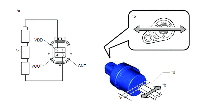
INSPECT SHIFT STROKE SENSOR |
(a) Connect 3 new dry-cell batteries (1.5 V each) in series.
(b) Prepare a magnet or equivalent tool.
(c) Remove the shift stroke sensor.
Click here
(d) Connect a positive (+) lead from the batteries to terminal 2 (VDD) and a negative (-) lead to terminal 3 (GND).
|
*a |
Component without harness connected (Shift Stroke Sensor) |
*b |
Magnet Movement Direction |
|
*c |
Dry Cell Battery |
*d |
Magnet |
|
*e |
2.6 mm or less |
- |
- |
(e) Wave the magnet left and right 2.6 mm (0.102 in.) or less from the tip of the shift stroke sensor to output a high/low signal while measuring the voltage.
(f) Measure the voltage according to the value(s) in the table below.
Standard Voltage (Combined Dry-cell Battery Voltage of 4.5 V):
|
Tester Connection |
Condition |
Specified Condition |
|---|---|---|
|
4 (VOUT) - 3 (GND) |
High signal |
4.09 to 4.19 V |
|
Low signal |
0.36 to 0.45 V |
Reference Voltage (Combined Dry-cell Battery Voltage of 5.0 V):
|
Tester Connection |
Condition |
Specified Condition |
|---|---|---|
|
4 (VOUT) - 3 (GND) |
High signal |
4.55 to 4.65 V |
|
Low signal |
0.4 to 0.5 V |
(g) Install the shift stroke sensor.
Click here
| NG | |
REPLACE SHIFT STROKE SENSOR |
|
|
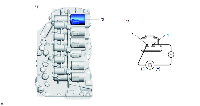
3. |
INSPECT TRANSMISSION VALVE BODY ASSEMBLY (SHIFT SOLENOID VALVE SLG) |
(a) Disconnect the transmission wire connector from the shift solenoid valve SLG.
Click here
|
*1 |
Transmission Valve Body Assembly |
*2 |
Shift Solenoid Valve SLG |
|
*a |
Component without harness connected (Shift Solenoid Valve SLG) |
- |
- |
(b) Connect a positive (+) lead from the auxiliary battery with a 21 W bulb to terminal 1 and a negative (-) lead to terminal 2 of the shift solenoid valve SLG connector. Check that the valve moves and makes an operating sound.
OK:
Valve moves and makes an operating sound.
| NG | |
GO TO STEP 5 |
|
|
4. |
REPLACE CONTINUOUSLY VARIABLE TRANSAXLE ASSEMBLY |
Click here
| NEXT | |
PERFORM REGISTRATION AND INITIALIZATION for Registration: Click here for Initialization: Click here |
|
5. |
REPLACE TRANSMISSION VALVE BODY ASSEMBLY |
Click here
| NEXT | |
PERFORM REGISTRATION AND INITIALIZATION for Registration: Click here for Initialization: Click here |


