Toyota Corolla Cross: Power Distribution Box Missing Message (B235587,B235787-B235987)
DESCRIPTION
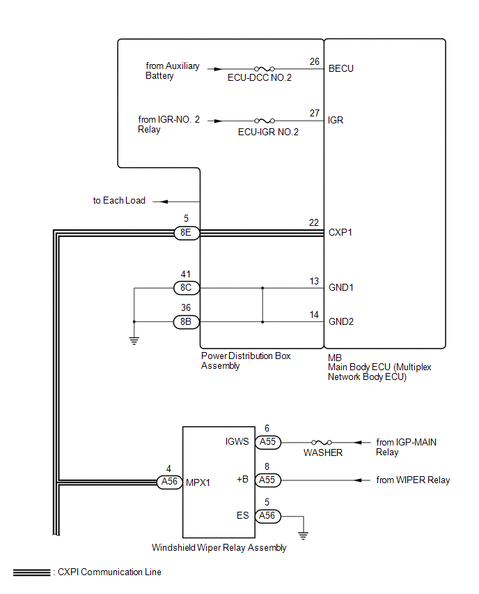
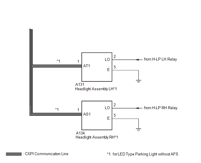
This DTC is stored when CXPI communication between the power distribution box assembly and windshield wiper relay assembly, headlight assembly RH*1, headlight assembly LH*1 or main body ECU (multiplex network body ECU) stops for 10 seconds or more.
- *1: for LED Type Parking Light without AFS
|
DTC No. |
Detection Item |
DTC Detection Condition |
Trouble Area |
|---|---|---|---|
|
B235587 |
Power Distribution Box Missing Message |
No communication between power distribution box assembly and main body ECU (multiplex network body ECU) for 10 seconds or more |
|
|
B235787 |
Wiper Module Missing Message |
No communication between windshield wiper relay assembly and main body ECU (multiplex network body ECU) for 10 seconds or more |
|
|
B235887 |
Smart LDM Left Missing Message |
No communication between headlight assembly LH and main body ECU (multiplex network body ECU) for 10 seconds or more |
|
|
B235987 |
Smart LDM Right Missing Message |
No communication between headlight assembly RH and main body ECU (multiplex network body ECU) for 10 seconds or more |
|
- *1: for LED Type Parking Light without AFS
WIRING DIAGRAM
CAUTION / NOTICE / HINT
NOTICE:
- Inspect the fuses for circuits related to this system before performing the following procedure.
- Recognition code registration is necessary when replacing the main body ECU (multiplex network body ECU).
- Before replacing the main body ECU (multiplex network body ECU), refer to
Registration.
- for HEV Model: Click here
.gif)
- for Gasoline Model: Click here
- for HEV Model: Click here
- When disconnecting and reconnecting the auxiliary battery.
HINT:
When disconnecting and reconnecting the auxiliary battery, there is an automatic learning function that completes learning when the respective system is used.
Click here
- Some parts must be initialized and set when replacing or removing and installing
parts.
Click here
PROCEDURE
|
1. |
CLEAR DTC |
(a) Clear the DTCs.
Body Electrical > Main Body > Clear DTCs
|
.gif)
|
2. |
CHECK FOR DTC |
(a) Check for DTCs.
Body Electrical > Main Body > Trouble Codes|
Result |
Proceed to |
|---|---|
|
B235587, B235787, B235887 and B235987 are output |
A |
|
B235787, B235887 and B235987 are output |
B |
|
Only B235787 is output |
C |
|
Only B235887 is output |
D |
|
Only B235987 is output |
E |
|
DTCs are not output |
F |
| B | .gif) |
GO TO STEP 4 |
| C | |
GO TO STEP 5 |
| D | |
GO TO STEP 7 |
| E | |
GO TO STEP 9 |
| F | |
USE SIMULATION METHOD TO CHECK |
|
|
3. |
CHECK POWER DISTRIBUTION BOX ASSEMBLY |
(a) Remove the power distribution box assembly.
HINT:
Click here
(b) Remove the main body ECU (multiplex network body ECU) from the power distribution box assembly.
(c) Disconnect the 8E power distribution box assembly connector.
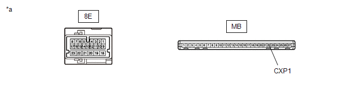
(d) Measure the resistance according to the value(s) in the table below.
|
*a |
Component without harness connected (Power Distribution Box Assembly) |
- |
- |
|
Tester Connection |
Condition |
Specified Condition |
|---|---|---|
|
MB-22 (CXP1) - 8E-5 |
Always |
Below 1 Ω |
| OK | |
REPLACE MAIN BODY ECU (MULTIPLEX NETWORK BODY ECU) |
| NG | |
REPLACE POWER DISTRIBUTION BOX ASSEMBLY |
|
4. |
CHECK HARNESS AND CONNECTOR (POWER DISTRIBUTION BOX ASSEMBLY - WINDSHIELD WIPER RELAY ASSEMBLY) |
(a) Disconnect the cable from the negative (-) auxiliary battery terminal.
(b) Disconnect the 8E power distribution box assembly connector.
(c) Disconnect the A56 windshield wiper relay assembly connector.
(d) Disconnect the A131 headlight assembly LH connector.*1
(e) Disconnect the A134 headlight assembly RH connector.*1
- *1: for LED Type Parking Light without AFS
(f) Measure the resistance according to the value(s) in the table below.
Standard Resistance:
|
Tester Connection |
Condition |
Specified Condition |
|---|---|---|
|
8E-5 - A56-4 (MPX1) |
Cable disconnected from negative (-) auxiliary battery terminal |
Below 1 Ω |
|
8E-5 - Body ground |
Cable disconnected from negative (-) auxiliary battery terminal |
10 kΩ or higher |
| OK | |
REPLACE MAIN BODY ECU (MULTIPLEX NETWORK BODY ECU) |
| NG | |
REPAIR OR REPLACE HARNESS OR CONNECTOR |
|
5. |
CHECK HARNESS AND CONNECTOR (WINDSHIELD WIPER RELAY ASSEMBLY - POWER DISTRIBUTION BOX ASSEMBLY) |
(a) Turn the ignition switch off.
(b) Disconnect the cable from the negative (-) auxiliary battery terminal.
(c) Disconnect the A56 windshield wiper relay assembly connector.
(d) Disconnect the 8E power distribution box assembly connector.
(e) Measure the resistance according to the value(s) in the table below.
Standard Resistance:
|
Tester Connection |
Condition |
Specified Condition |
|---|---|---|
|
A56-4 (MPX1) - 8E-5 |
Cable disconnected from negative (-) auxiliary battery terminal |
Below 1 Ω |
|
A56-4 (MPX1) - Body ground |
Cable disconnected from negative (-) auxiliary battery terminal |
10 kΩ or higher |
| NG | |
REPAIR OR REPLACE HARNESS OR CONNECTOR |
|
|
6. |
CHECK HARNESS AND CONNECTOR (WINDSHIELD WIPER RELAY ASSEMBLY - BATTERY AND BODY GROUND) |
(a) Disconnect the A55 and A56 windshield wiper relay assembly connectors.
(b) Measure the resistance according to the value(s) in the table below.
Standard Resistance:
|
Tester Connection |
Condition |
Specified Condition |
|---|---|---|
|
A56-5 (ES) - Body ground |
Always |
Below 1 Ω |
(c) Connect the cable to the negative (-) auxiliary battery terminal.
(d) Measure the voltage according to the value(s) in the table below.
Standard Voltage:
|
Tester Connection |
Switch Condition |
Specified Condition |
|---|---|---|
|
A55-6 (IGWS) - Body ground |
Ignition switch ON |
11 to 14 V |
|
A55-8 (+B) - Body ground |
Ignition switch ON |
11 to 14 V |
| OK | |
REPLACE WINDSHIELD WIPER RELAY ASSEMBLY |
| NG | |
REPAIR OR REPLACE HARNESS OR CONNECTOR |
|
7. |
CHECK HARNESS AND CONNECTOR (HEADLIGHT ASSEMBLY LH - POWER DISTRIBUTION BOX ASSEMBLY) |
(a) Turn the ignition switch off.
(b) Disconnect the cable from the negative (-) auxiliary battery terminal.
(c) Disconnect the A131 headlight assembly LH connector.
(d) Disconnect the 8E power distribution box assembly connector.
(e) Measure the resistance according to the value(s) in the table below.
Standard Resistance:
|
Tester Connection |
Condition |
Specified Condition |
|---|---|---|
|
A131-1 (AT1) - 8E-5 |
Cable disconnected from negative (-) auxiliary battery terminal |
Below 1 Ω |
|
A131-1 (AT1) - Body ground |
Cable disconnected from negative (-) auxiliary battery terminal |
10 kΩ or higher |
| NG | |
REPAIR OR REPLACE HARNESS OR CONNECTOR |
|
|
8. |
CHECK HARNESS AND CONNECTOR (HEADLIGHT ASSEMBLY LH - BATTERY AND BODY GROUND) |
(a) Measure the resistance according to the value(s) in the table below.
Standard Resistance:
|
Tester Connection |
Condition |
Specified Condition |
|---|---|---|
|
A131-5 (E) - Body ground |
Always |
Below 1 Ω |
(b) Connect the cable to the negative (-) auxiliary battery terminal.
(c) Measure the voltage according to the value(s) in the table below.
Standard Voltage:
|
Tester Connection |
Switch Condition |
Specified Condition |
|---|---|---|
|
A131-2 (LO) - Body ground |
Ignition switch off |
11 to 14 V |
| OK | |
REPLACE HEADLIGHT ASSEMBLY LH |
| NG | |
REPAIR OR REPLACE HARNESS OR CONNECTOR |
|
9. |
CHECK HARNESS AND CONNECTOR (HEADLIGHT ASSEMBLY RH - POWER DISTRIBUTION BOX ASSEMBLY) |
(a) Turn the ignition switch off.
(b) Disconnect the cable from the negative (-) auxiliary battery terminal.
(c) Disconnect the A134 headlight assembly RH connector.
(d) Disconnect the 8E power distribution box assembly connector.
(e) Measure the resistance according to the value(s) in the table below.
Standard Resistance:
|
Tester Connection |
Condition |
Specified Condition |
|---|---|---|
|
A134-1 (AS1) - 8E-5 |
Cable disconnected from negative (-) auxiliary battery terminal |
Below 1 Ω |
|
A134-1 (AS1) - Body ground |
Cable disconnected from negative (-) auxiliary battery terminal |
10 kΩ or higher |
| NG | |
REPAIR OR REPLACE HARNESS OR CONNECTOR |
|
|
10. |
CHECK HARNESS AND CONNECTOR (HEADLIGHT ASSEMBLY RH - BATTERY AND BODY GROUND) |
(a) Measure the resistance according to the value(s) in the table below.
Standard Resistance:
|
Tester Connection |
Condition |
Specified Condition |
|---|---|---|
|
A134-5 (E) - Body ground |
Always |
Below 1 Ω |
(b) Connect the cable to the negative (-) auxiliary battery terminal.
(c) Measure the voltage according to the value(s) in the table below.
Standard Voltage:
|
Tester Connection |
Switch Condition |
Specified Condition |
|---|---|---|
|
A134-2 (LO) - Body ground |
Ignition switch off |
11 to 14 V |
| OK | |
REPLACE HEADLIGHT ASSEMBLY RH |
| NG | |
REPAIR OR REPLACE HARNESS OR CONNECTOR |


