Toyota Corolla Cross Owners & Service Manuals

Toyota Corolla Cross: Parts Location

PARTS LOCATION

ILLUSTRATION

*1

BRAKE ACTUATOR ASSEMBLY

- SKID CONTROL ECU

*2

ECM

*3

NO. 1 ENGINE ROOM RELAY BLOCK

- ABS NO. 2 FUSE

*4

TCM

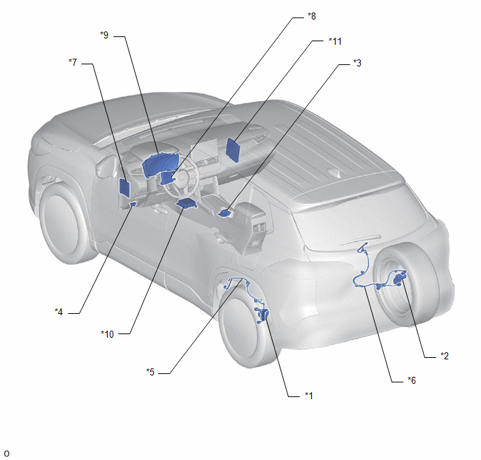
ILLUSTRATION

*1

PARKING BRAKE ACTUATOR ASSEMBLY LH

*2

PARKING BRAKE ACTUATOR ASSEMBLY RH

*3

ELECTRIC PARKING BRAKE SWITCH (ELECTRIC PARKING BRAKE SWITCH ASSEMBLY)

*4

DLC3

*5

NO. 2 PARKING BRAKE WIRE ASSEMBLY

*6

NO. 1 PARKING BRAKE WIRE ASSEMBLY

*7

MAIN BODY ECU (MULTIPLEX NETWORK BODY ECU)

*8

AIR CONDITIONING AMPLIFIER ASSEMBLY

*9

COMBINATION METER ASSEMBLY

*10

DECELERATION SENSOR (AIRBAG ECU ASSEMBLY)

*11

ENGINE STOP AND START ECU

-

-

    READ NEXT:

     System Diagram

    SYSTEM DIAGRAM

     How To Proceed With Troubleshooting

    CAUTION / NOTICE / HINT HINT: *: Use the GTS. PROCEDURE 1. VEHICLE BROUGHT TO WORKSHOP NEXT

     Test Mode Procedure

    TEST MODE PROCEDURE REAR BRAKE PAD REPLACEMENT MODE *1 Rear Disc Brake Piston *2 Nut *a The nut moves inward in pad re

    SEE MORE:

     Rear Television Camera Communication Stop Mode

    DESCRIPTION Detection Item Symptom Trouble Area Rear Television Camera Communication Stop Mode Communication stop for "Parking Assist Monitor System / Rear Camera" is indicated on the "Communication Bus Check" scre

     High Voltage Power Resource Circuit Voltage Sensor after Boosting Malfunction (P1C8349)

    DTC SUMMARY MALFUNCTION DESCRIPTION The hybrid vehicle control ECU monitors the high-voltage wiring between the HV battery and inverter with converter assembly and detects a power supply malfunction. The cause of this malfunction may be one of the following: Inverter voltage sensor (VL) internal

    © 2020-2025 Copyright www.tcorollacross.com PT NL