Toyota Corolla Cross: Left Rear Wheel Speed Sensor Internal Electronic Failure (C050C49)
DESCRIPTION
When the system is starting up and the skid control ECU (brake actuator assembly) detects a speed sensor circuit malfunction via the speed sensor circuit self-diagnosis function, this DTC is stored.
|
DTC No. |
Detection Item |
DTC Detection Condition |
Trouble Area |
MIL |
DTC Output from |
Note |
|---|---|---|---|---|---|---|
|
C050C49 |
Left Rear Wheel Speed Sensor Internal Electronic Failure |
A circuit malfunction in the speed sensor is detected during the self-test. |
|
Comes on |
Brake/EPB |
|
MONITOR DESCRIPTION
The skid control ECU (brake actuator assembly) has a speed sensor circuit self-diagnosis function.
When the self-diagnosis function that is performed during system startup detects a speed sensor circuit malfunction, the skid control ECU (brake actuator assembly) illuminates the MIL and stores this DTC.
MONITOR STRATEGY
|
Related DTCs |
C050C: Wheel speed sensor start up test for RL |
|
Required Sensors/Components(Main) |
Skid control ECU (brake actuator assembly) |
|
Required Sensors/Components(Related) |
Skid control ECU (brake actuator assembly) |
|
Frequency of Operation |
During initial checking |
|
Duration |
- |
|
MIL Operation |
Immediately |
|
Sequence of Operation |
None |
TYPICAL ENABLING CONDITIONS
|
Monitor runs whenever the following DTCs are not stored |
TMC's intellectual property |
|
Other conditions belong to TMC's intellectual property |
- |
TYPICAL MALFUNCTION THRESHOLDS
|
TMC's intellectual property |
- |
COMPONENT OPERATING RANGE
|
TMC's intellectual property |
- |
CONFIRMATION DRIVING PATTERN
NOTICE:
When performing the normal judgment procedure, make sure that the driver door is closed and is not opened at any time during the procedure.
HINT:
- After repair has been completed, clear the DTC and then check that the vehicle has returned to normal by performing the following All Readiness check procedure.
- When clearing the permanent DTCs, refer to the "CLEAR PERMANENT DTC" procedure.
- Connect the GTS to the DLC3.
- Turn the ignition switch to ON and turn the GTS on.
- Clear the DTCs (even if no DTCs are stored, perform the clear DTC procedure).
- Turn the ignition switch off.
- Turn the ignition switch to ON (READY) and turn the GTS on.
- Wait for 1 second or more. [*]
HINT:
[*]: Normal judgment procedure.
The normal judgment procedure is used to complete DTC judgment and also used when clearing permanent DTCs.
- Enter the following menus: Chassis / Brake/EPB* / Utility / All Readiness.
*: Electric Parking Brake System
- Check the DTC judgment result.
HINT:
- If the judgment result shows NORMAL, the system is normal.
- If the judgment result shows ABNORMAL, the system has a malfunction.
- If the judgment result shows INCOMPLETE, perform driving pattern again.
WIRING DIAGRAM
Refer to DTC C050C12.
Click here .gif)
PROCEDURE
|
1. |
CHECK HARNESS AND CONNECTOR (SENSOR CIRCUIT) |
|
(a) Make sure that there is no looseness at the locking part and the connecting part of the connectors. OK: The connector is securely connected. |
|
.png)
(b) Disconnect the n4 rear speed sensor LH connector.
(c) Check both the connector case and the terminals for deformation and corrosion.
OK:
No deformation or corrosion.
(d) Turn the ignition switch to ON.
(e) Measure the voltage according to the value(s) in the table below.
Standard Voltage:
|
Tester Connection |
Condition |
Specified Condition |
|---|---|---|
|
n4-1 (RL+) - n4-2 (RL-) |
Ignition switch ON |
11 to 14 V |
| NG | .gif)
|
GO TO STEP 7 |
|
.gif)
|
2. |
CHECK HARNESS AND CONNECTOR (SENSOR POWER SOURCE CIRCUIT) |
|
(a) Make sure that there is no looseness at the locking part and the connecting part of the connectors. OK: The connector is securely connected. |
|
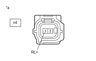
(b) Disconnect the n4 rear speed sensor LH connector.
(c) Check both the connector case and the terminals for deformation and corrosion.
OK:
No deformation or corrosion.
(d) Turn the ignition switch to ON.
(e) Measure the voltage according to the value(s) in the table below.
Standard Voltage:
|
Tester Connection |
Condition |
Specified Condition |
|---|---|---|
|
n4-1 (RL+) - Body ground |
Ignition switch off |
Below 1.5 V |
| NG |
|
GO TO STEP 5 |
|
|
3. |
INSPECT NO. 2 PARKING BRAKE WIRE ASSEMBLY |
|
(a) Make sure that there is no looseness at the locking part and the connecting part of the connectors. OK: The connector is securely connected. |
|
.png)
(b) Disconnect the n4 skid control sensor wire LH (No. 2 parking brake wire assembly) connector.
(c) Disconnect the nO2 skid control sensor wire LH (No. 2 parking brake wire assembly) connector.
(d) Check both the connector case and the terminals for deformation and corrosion.
OK:
No deformation or corrosion.
(e) Measure the resistance according to the value(s) in the table below.
Standard Resistance:
|
Tester Connection |
Condition |
Specified Condition |
|---|---|---|
|
n4-2 (RL-) or nO2-1 (RL-) - Body ground and other terminals |
Always |
10 kΩ or higher |
| NG |
|
REPLACE NO. 2 PARKING BRAKE WIRE ASSEMBLY |
|
|
4. |
CHECK HARNESS AND CONNECTOR (NO. 2 PARKING BRAKE WIRE ASSEMBLY - BRAKE ACTUATOR ASSEMBLY) |
(a) Make sure that there is no looseness at the locking part and the connecting part of the connectors.
OK:
The connector is securely connected.
(b) Disconnect the A151 skid control ECU (brake actuator assembly) connector.
(c) Disconnect the nO2 skid control sensor wire LH (No. 2 parking brake wire assembly) connector.
(d) Check both the connector case and the terminals for deformation and corrosion.
OK:
No deformation or corrosion.
(e) Measure the resistance according to the value(s) in the table below.
Standard Resistance:
|
Tester Connection |
Condition |
Specified Condition |
|---|---|---|
|
nO2-1 (RL-) or A151-23 (RL-) - Body ground |
Always |
10 kΩ or higher |
| OK |
|
REPLACE REAR SPEED SENSOR LH |
| NG |
|
REPAIR OR REPLACE HARNESS OR CONNECTOR |
|
5. |
CHECK HARNESS AND CONNECTOR (SENSOR POWER SOURCE CIRCUIT) |
|
(a) Make sure that there is no looseness at the locking part and the connecting part of the connectors. OK: The connector is securely connected. |
|
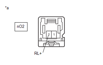
(b) Disconnect the nO2 skid control sensor wire LH (No. 2 parking brake wire assembly) connector.
(c) Check both the connector case and the terminals for deformation and corrosion.
OK:
No deformation or corrosion.
(d) Measure the voltage according to the value(s) in the table below.
Standard Voltage:
|
Tester Connection |
Condition |
Specified Condition |
|---|---|---|
|
nO2-2 (RL+) - Body ground |
Ignition switch off |
Below 1.5 V |
| OK |
|
REPLACE NO. 2 PARKING BRAKE WIRE ASSEMBLY |
|
|
6. |
CHECK HARNESS AND CONNECTOR (NO. 2 PARKING BRAKE WIRE ASSEMBLY - BRAKE ACTUATOR ASSEMBLY) |
|
(a) Make sure that there is no looseness at the locking part and the connecting part of the connectors. OK: The connector is securely connected. |
|
(b) Disconnect the A151 skid control ECU (brake actuator assembly) connector.
(c) Disconnect the nO2 skid control sensor wire LH (No. 2 parking brake wire assembly) connector.
(d) Check both the connector case and the terminals for deformation and corrosion.
OK:
No deformation or corrosion.
(e) Measure the voltage according to the value(s) in the table below.
Standard Voltage:
|
Tester Connection |
Condition |
Specified Condition |
|---|---|---|
|
nO2-2 (RL+) - Body ground |
Always |
Below 1.5 V |
| OK |
|
REPLACE BRAKE ACTUATOR ASSEMBLY |
| NG |
|
REPAIR OR REPLACE HARNESS OR CONNECTOR |
|
7. |
CHECK HARNESS AND CONNECTOR (SENSOR CIRCUIT) |
|
(a) Make sure that there is no looseness at the locking part and the connecting part of the connectors. OK: The connector is securely connected. |
|
.png)
(b) Disconnect the nO2 skid control sensor wire LH (No. 2 parking brake wire assembly) connector.
(c) Check both the connector case and the terminals for deformation and corrosion.
OK:
No deformation or corrosion.
(d) Turn the ignition switch to ON.
(e) Measure the voltage according to the value(s) in the table below.
Standard Voltage:
|
Tester Connection |
Condition |
Specified Condition |
|---|---|---|
|
nO2-2 (RL+) - nO2-1 (RL-) |
Ignition switch ON |
11 to 14 V |
| OK |
|
REPLACE NO. 2 PARKING BRAKE WIRE ASSEMBLY |
|
|
8. |
CHECK HARNESS AND CONNECTOR (SENSOR POWER SOURCE CIRCUIT) |
|
(a) Make sure that there is no looseness at the locking part and the connecting part of the connectors. OK: The connector is securely connected. |
|
(b) Disconnect the nO2 skid control sensor wire LH (No. 2 parking brake wire assembly) connector.
(c) Check both the connector case and the terminals for deformation and corrosion.
OK:
No deformation or corrosion.
(d) Turn the ignition switch to ON.
(e) Measure the voltage according to the value(s) in the table below.
Standard Voltage:
|
Tester Connection |
Condition |
Specified Condition |
|---|---|---|
|
nO2-2 (RL+) - Body ground |
Ignition switch ON |
11 to 14 V |
| NG |
|
GO TO STEP 11 |
|
|
9. |
CHECK HARNESS AND CONNECTOR (NO. 2 PARKING BRAKE WIRE ASSEMBLY - BRAKE ACTUATOR ASSEMBLY) |
|
(a) Make sure that there is no looseness at the locking part and the connecting part of the connectors. OK: The connector is securely connected. |
|
.png)
(b) Disconnect the A151 skid control ECU (brake actuator assembly) connector.
(c) Disconnect the nO2 skid control sensor wire LH (No. 2 parking brake wire assembly) connector.
(d) Check both the connector case and the terminals for deformation and corrosion.
OK:
No deformation or corrosion.
(e) Measure the voltage according to the value(s) in the table below.
Standard Voltage:
|
Tester Connection |
Condition |
Specified Condition |
|---|---|---|
|
nO2-1 (RL-) - Body ground |
Always |
Below 1.5 V |
| NG |
|
REPAIR OR REPLACE HARNESS OR CONNECTOR |
|
|
10. |
CHECK HARNESS AND CONNECTOR (NO. 2 PARKING BRAKE WIRE ASSEMBLY - BRAKE ACTUATOR ASSEMBLY) |
(a) Make sure that there is no looseness at the locking part and the connecting part of the connectors.
OK:
The connector is securely connected.
(b) Disconnect the A151 skid control ECU (brake actuator assembly) connector.
(c) Disconnect the nO2 skid control sensor wire LH (No. 2 parking brake wire assembly) connector.
(d) Check both the connector case and the terminals for deformation and corrosion.
OK:
No deformation or corrosion.
(e) Measure the resistance according to the value(s) in the table below.
Standard Resistance:
|
Tester Connection |
Condition |
Specified Condition |
|---|---|---|
|
nO2-1 (RL-) - A151-23 (RL-) |
Always |
Below 1 Ω |
|
nO2-2 (RL+) or A151-39 (RL+) - nO2-1 (RL-) or A151-23 (RL-) |
Always |
10 kΩ or higher |
| OK |
|
REPLACE BRAKE ACTUATOR ASSEMBLY |
| NG |
|
REPAIR OR REPLACE HARNESS OR CONNECTOR |
|
11. |
CHECK HARNESS AND CONNECTOR (NO. 2 PARKING BRAKE WIRE ASSEMBLY - BRAKE ACTUATOR ASSEMBLY) |
(a) Make sure that there is no looseness at the locking part and the connecting part of the connectors.
OK:
The connector is securely connected.
(b) Disconnect the A151 skid control ECU (brake actuator assembly) connector.
(c) Disconnect the nO2 skid control sensor wire LH (No. 2 parking brake wire assembly) connector.
(d) Check both the connector case and the terminals for deformation and corrosion.
OK:
No deformation or corrosion.
(e) Measure the resistance according to the value(s) in the table below.
Standard Resistance:
|
Tester Connection |
Condition |
Specified Condition |
|---|---|---|
|
nO2-2 (RL+) - A151-39 (RL+) |
Always |
Below 1 Ω |
|
nO2-2 (RL+) or A151-39 (RL+) - Body ground |
Always |
10 kΩ or higher |
| OK |
|
REPLACE BRAKE ACTUATOR ASSEMBLY |
| NG |
|
REPAIR OR REPLACE HARNESS OR CONNECTOR |


