Toyota Corolla Cross: Installation
INSTALLATION
CAUTION / NOTICE / HINT
COMPONENTS (INSTALLATION)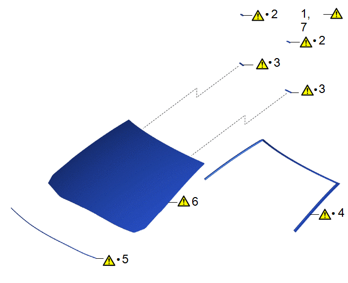
|
Procedure | Part Name Code |
.png) |
.png) |
 |
|---|---|---|---|---|---|
|
1 | CLEAN WINDSHIELD GLASS SUB-ASSEMBLY |
- |
|
- | - |
|
2 | NO. 1 WINDSHIELD GLASS STOPPER |
56115A |
|
- | - |
|
3 | NO. 2 WINDSHIELD GLASS STOPPER |
56116C |
|
- | - |
|
4 | WINDSHIELD OUTSIDE MOULDING |
75533G |
|
- | - |
|
5 | WINDOW GLASS ADHESIVE DAM |
56117A |
|
- | - |
|
6 | WINDSHIELD GLASS SUB-ASSEMBLY |
- |
|
- | - |
|
7 | INSPECT FOR LEAK |
- |
|
- | - |
|
● | Non-reusable part |
- | - |
|
Procedure | Part Name Code |
|
|
| |
|---|---|---|---|---|---|
|
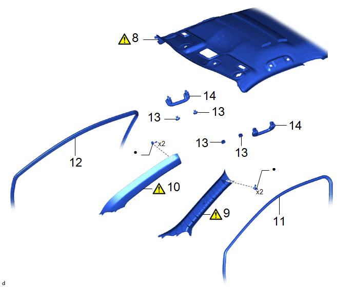
8 | ROOF HEADLINING ASSEMBLY |
63311C |
|
- | - |
|
9 | FRONT PILLAR GARNISH ASSEMBLY LH |
62212B |
|
- | - |
|
10 | FRONT PILLAR GARNISH ASSEMBLY RH |
62211U |
|
- | - |
|
11 | FRONT DOOR OPENING TRIM WEATHERSTRIP LH |
62312B | - |
- | - |
|
12 | FRONT DOOR OPENING TRIM WEATHERSTRIP RH |
62311B | - |
- | - |
|
13 | ASSIST GRIP COVER |
74612 | - |
- | - |
|
14 | ASSIST GRIP SUB-ASSEMBLY |
74610A | - |
- | - |
|
● | Non-reusable part |
- | - |

|
Procedure | Part Name Code |
|
|
| |
|---|---|---|---|---|---|
|
15 | VISOR HOLDER |
74348 | - |
- | - |
|
16 | VISOR ASSEMBLY LH |
74320 | - |
- | - |
|
17 | VISOR ASSEMBLY RH |
74310 | - |
- | - |
|
18 | MAP LIGHT ASSEMBLY |
81260A | - |
- | - |
|
19 | INNER REAR VIEW MIRROR ASSEMBLY |
87810 | - |
- | - |
|
20 | INSTALL FORWARD RECOGNITION CAMERA |
8646C | - |
- | - |
|
21 | COWL TOP VENTILATOR LOUVER SUB-ASSEMBLY |
55708 | - |
- | - |
|
22 | ADJUST FORWARD RECOGNITION CAMERA |
8646C | - |
- |
|
CAUTION / NOTICE / HINT
NOTICE:
- When replacing the windshield glass of a vehicle equipped with a forward recognition camera, make sure to use a Toyota genuine part. If a non-Toyota genuine part is used, the forward recognition camera may not be able to be installed due to a missing bracket. Also, the dynamic radar cruise control system, lane tracing assist system, pre-collision system, road sign assist system, front camera system or automatic high beam system may not operate properly due to a difference in the transmissivity or black ceramic border.
- Make sure to use Toyota Genuine Windshield Glass Adhesive (High Modulus Type) or equivalent.
PROCEDURE
1. CLEAN WINDSHIELD GLASS SUB-ASSEMBLY
.png)
(1) When reusing the windshield glass sub-assembly.
1. Using a scraper, remove any remaining adhesive dam and adhesive residue from the windshield glass sub-assembly.
NOTICE:
Be careful not to damage the windshield glass sub-assembly.
(2) Clean the outer circumference of the windshield glass sub-assembly with a non-residue solvent.
NOTICE:
- Do not touch the windshield glass sub-assembly surface after cleaning it.
- Even if using a new windshield glass sub-assembly, clean it with a non-residue solvent.
2. INSTALL NO. 1 WINDSHIELD GLASS STOPPER
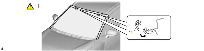
|
*1 | No. 1 windshield glass stopper |
- | - |
(1) Install 2 new No. 1 windshield glass stoppers to the vehicle body as shown in the illustration.
HINT:
Only 2-piece type windshield glass stoppers are provided as supply parts. Use 2-piece type stoppers as replacements even if 1-piece type stoppers were originally installed.
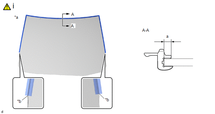
3. INSTALL NO. 2 WINDSHIELD GLASS STOPPER
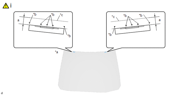
|
*a | Back Side of Windshield Glass Sub-assembly |
*b | Ceramic Notch |
|
*c | Windshield Glass Edge Side |
- | - |
(1) Install the No. 2 windshield glass stopper by below procedure.
1. Using a brush or sponge, coat the installation area of the No. 2 windshield glass stoppers with glass primer.
NOTICE:
- Do not apply too much glass primer.
- Allow the glass primer to dry for 3 minutes or more.
- Throw away any leftover glass primer.
HINT:
If an area other than specified is coated by accident, wipe off the glass primer with a clean piece of cloth before it dries.
2. Install 2 new No. 2 windshield glass stoppers to the windshield glass sub-assembly as shown in the illustration.
Standard Dimension:
|
Area | Dimension |
Area | Dimension |
|---|---|---|---|
|
a | 11.1 mm (0.437 in.) |
- | - |
HINT:
Only 2-piece type windshield glass stoppers are provided as supply parts. Use 2-piece type stoppers as replacements even if 1-piece type stoppers were originally installed.
4. INSTALL WINDSHIELD OUTSIDE MOULDING
|
*a | Back Side of Windshield Glass Sub-assembly |
*b | R End |
(1) Install the windshield outside moulding by the below procedure.
1. Using a brush or sponge, coat the installation area of the windshield outside moulding with glass primer.
NOTICE:
- Do not apply too much glass primer.
- Allow the glass primer to dry for 3 minutes or more.
- Throw away any leftover glass primer.
HINT:
If an area other than specified is coated by accident, wipe off the glass primer with a clean piece of cloth before it dries.
2. Install a new windshield outside moulding to the windshield glass sub-assembly as shown in the illustration.
Standard Dimension:
|
Area | Dimension |
Area | Dimension |
|---|---|---|---|
|
a | 4.5 mm (0.177 in.) |
- | - |
5. INSTALL WINDOW GLASS ADHESIVE DAM
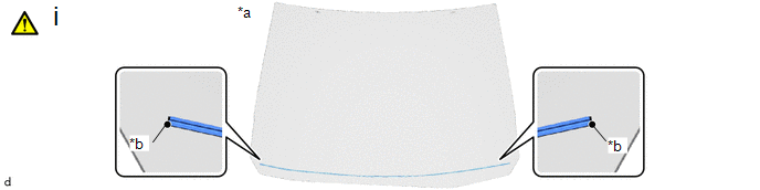
|
*a | Back Side of Windshield Glass Sub-assembly |
*b | Ceramic Notch |
(1) Install the window glass adhesive by the below procedure.
1. Using a brush or sponge, coat the installation area of the window glass adhesive dam with glass primer.
NOTICE:
- Do not apply too much glass primer.
- Allow the glass primer to dry for 3 minutes or more.
- Throw away any leftover glass primer.
HINT:
If an area other than specified is coated by accident, wipe off the glass primer with a clean piece of cloth before it dries.
2. Install a new window glass adhesive dam to the windshield glass sub-assembly as shown in the illustration.
6. INSTALL WINDSHIELD GLASS SUB-ASSEMBLY
.png) |
Adhesive | - |
- |
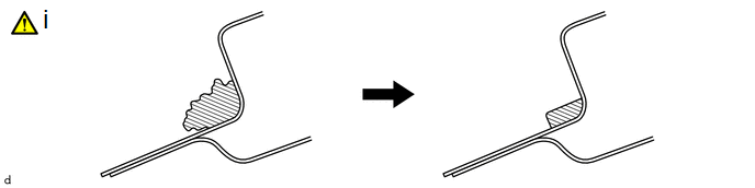
(1) Clean and shape the contact surface of the vehicle body by the below procedure.
1. Using a knife, cut away excess adhesive on the contact surface of the vehicle body as shown in the illustration.
NOTICE:
Leave as much adhesive on the vehicle body as possible.
2. Clean the contact surface of the vehicle body with a piece of cloth saturated with non-residue solvent.

|
*a | Matchmark |
*b | Suction Cup |
(1) Prepare to install the windshield glass sub-assembly by the below procedure.
1. Using suction cups, place the windshield glass sub-assembly in the correct position.
2. Check that the whole contact surface of the windshield glass sub-assembly rim is perfectly even.
3. Align the matchmarks on the windshield glass sub-assembly and vehicle body.
NOTICE:
Check that the windshield glass stoppers are engaged to the vehicle body correctly.
4. Remove the windshield glass sub-assembly.
5. Using a brush, coat the installation surface on the vehicle body with body primer.
NOTICE:
- Do not coat the adhesive with body primer.
- Do not apply too much body primer.
- Allow the body primer to dry for 3 minutes or more.
- Throw away any leftover body primer.
HINT:
If an area other than specified is coated by accident, wipe off the body primer with a clean piece of cloth before it dries.
|
*1 | Window Glass Adhesive Dam |
- | - |
|
*a | Back Side of Windshield Glass Sub-assembly |
- | - |
|
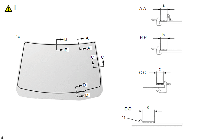
|
Glass Primer | - |
- |
(1) Using a brush or sponge, coat the adhesive application area with glass primer as shown in the illustration.
Standard Dimension:
|
Area | Dimension |
Area | Dimension |
|---|---|---|---|
|
a | 8.0 mm (0.315 in.) or more |
b | 9.1 mm (0.358 in.) or more |
|
c | 8.5 mm (0.335 in.) or more |
d | 19 mm (0.748 in.) or more |
NOTICE:
- Do not apply too much glass primer.
- Allow the glass primer to dry for 3 minutes or more.
- Throw away any leftover glass primer.
HINT:
- Apply glass primer to the ceramic notches.
- If an area other than specified is coated by accident, wipe off the glass primer with a clean piece of cloth before it dries.

|
*a | Cartridge Nozzle |
- | - |
|
|
Adhesive | - |
- |
(1) Prepare to apply adhesive to the windshield glass sub-assembly by the below procedure.
Adhesive:
Toyota Genuine Windshield Glass Adhesive (High modulus type) or equivalent
1. Cut off the tip of the cartridge nozzle as shown in the illustration.
Standard Dimension:
|
Area | Dimension |
Area | Dimension |
|---|---|---|---|
|
a | 12 to 15 mm (0.472 to 0.591 in.) |
b | 8.0 to 11 mm (0.315 to 0.433 in.) |
2. Load the sealer gun with the cartridge.

|
*1 | Window Glass Adhesive Dam |
- | - |
|
*a | Back Side of Windshield Glass Sub-assembly |
- | - |
|
|
Adhesive | - |
- |
(1) Apply adhesive to the windshield glass sub-assembly as shown in the illustration.
Standard Dimension:
|
Area | Dimension |
Area | Area |
|---|---|---|---|
|
a | 10.5 mm (0.413 in.) |
b | 10.5 mm (0.413 in.) |
|
c | 9.0 mm (0.354 in.) |
d | 16 mm (0.630 in.) |

|
*a | Matchmark |
*b | Suction Cup |
(1) Install the windshield glass sub-assembly by the below procedure.
1. Using suction cups, position the windshield glass sub-assembly so that the matchmarks are aligned, and press it in gently along the rim.
NOTICE:
- Check that the windshield glass stoppers are engaged to the vehicle body correctly.
- Check the clearance between the vehicle body and windshield glass sub-assembly.
2. Lightly press the outer surface of the windshield glass sub-assembly to ensure that the windshield glass sub-assembly is securely fit to the vehicle body.
HINT:
Press the glass with a force of 98 N (10 kgf, 22.0 lbf) or more.
3. Using a scraper, remove any excess or protruding adhesive.
4. Hold the windshield glass sub-assembly using protective tape until the applied adhesive becomes hard.
HINT:
Follow the instructions supplied by the adhesive manufacturer or in the corresponding instruction manual for the minimum amount of time necessary to wait before driving the vehicle.
7. INSPECT FOR LEAK
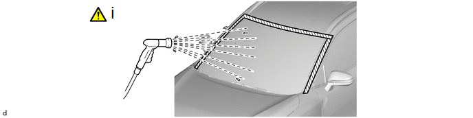
(1) Inspect for leaks by the below procedure.
1. After the adhesive has hardened, apply water from the outside of the vehicle. Check that no water leaks into the cabin.
2. If water leaks into the cabin, allow the water to dry and add adhesive.
3. Remove the protective tape.
8. INSTALL ROOF HEADLINING ASSEMBLY
|
|
NOTICE: Do not damage the roof headlining assembly or vehicle interior. |

(1) Return the front section of the roof headlining assembly to its original position.
9. INSTALL FRONT PILLAR GARNISH ASSEMBLY LH
|
|
Click here |
10. INSTALL FRONT PILLAR GARNISH ASSEMBLY RH
11. INSTALL FRONT DOOR OPENING TRIM WEATHERSTRIP LH
12. INSTALL FRONT DOOR OPENING TRIM WEATHERSTRIP RH
13. INSTALL ASSIST GRIP COVER
Click here .gif)
14. INSTALL ASSIST GRIP SUB-ASSEMBLY
15. INSTALL VISOR HOLDER
16. INSTALL VISOR ASSEMBLY LH
17. INSTALL VISOR ASSEMBLY RH
18. INSTALL MAP LIGHT ASSEMBLY
Click here
19. INSTALL INNER REAR VIEW MIRROR ASSEMBLY
- w/ EC Mirror:
Click here
- w/o EC Mirror:
Click here
20. INSTALL FORWARD RECOGNITION CAMERA
Click here
21. INSTALL COWL TOP VENTILATOR LOUVER SUB-ASSEMBLY
Click here
22. ADJUST FORWARD RECOGNITION CAMERA
(a) If the forward recognition camera has been replaced with a new one or the windshield glass has been removed and installed, it is necessary to perform Forward Recognition Camera Learning.
HINT:
Forward Recognition Camera Learning can be performed by using either Adjustment (One Time Recognition) or Adjustment (Driving Adjustment).
- One Time Recognition:
Click here
- Driving Adjustment:
Click here


