Toyota Corolla Cross: Installation
INSTALLATION
CAUTION / NOTICE / HINT
COMPONENTS (INSTALLATION)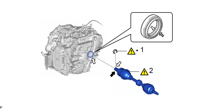
|
Procedure |
Part Name Code |
.png) |
.png) |
.png) |
|
|---|---|---|---|---|---|
|
1 |
FRONT DRIVE SHAFT HOLE SNAP RING |
43420G |
|
- |
- |
|
2 |
INSTALL FRONT DRIVE SHAFT ASSEMBLY |
43420 |
|
- |
- |
|
● |
Non-reusable part |
.png) |
Toyota Genuine CVT Fluid FE |
.png) |
MP Grease |
.png) |
Toyota Genuine Oil Seal Side Lip Grease |
|
Procedure |
Part Name Code |
|
|
|
|
|---|---|---|---|---|---|
|
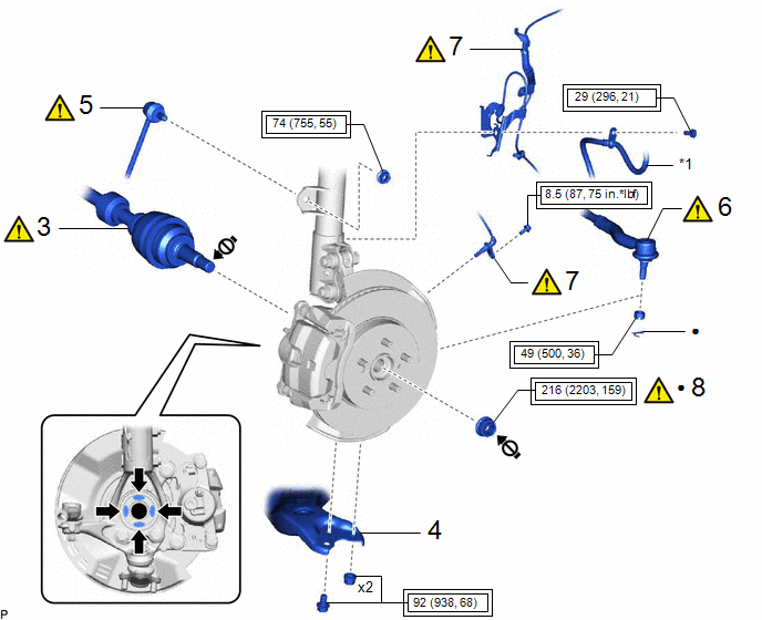
3 |
CONNECT FRONT DRIVE SHAFT ASSEMBLY |
43420 |
|
- |
- |
|
4 |
FRONT LOWER NO. 1 SUSPENSION ARM SUB-ASSEMBLY |
48069 |
- |
- |
- |
|
5 |
FRONT STABILIZER LINK ASSEMBLY |
48810 |
|
- |
- |
|
6 |
TIE ROD END SUB-ASSEMBLY |
45047 |
|
- |
- |
|
7 |
FRONT SPEED SENSOR |
89543 |
|
- |
- |
|
8 |
FRONT AXLE SHAFT NUT |
43502H |
|
- |
- |
|
*1 |
FRONT FLEXIBLE HOSE |
- |
- |
.png) |
Tightening torque for "Major areas involving basic vehicle performance such as moving/turning/stopping": N*m (kgf*cm, ft.*lbf) |
● |
Non-reusable part |
|
|
Toyota Body Grease W |
.png) |
Do not apply lubricants to the threaded parts |
|
Procedure |
Part Name Code |
|
|
|
|
|---|---|---|---|---|---|
|
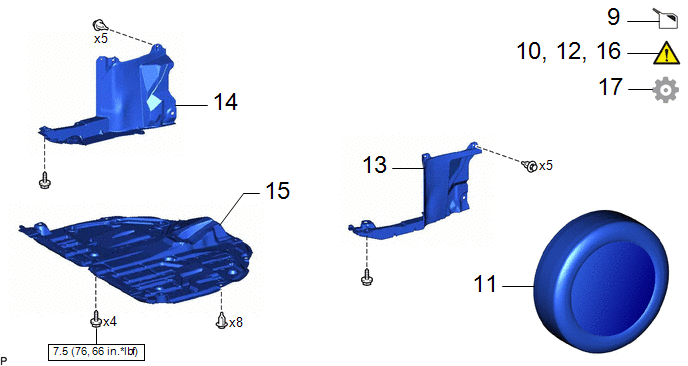
9 |
ADD CONTINUOUSLY VARIABLE TRANSAXLE FLUID |
- |
- |
|
- |
|
10 |
INSPECT FOR CONTINUOUSLY VARIABLE TRANSAXLE FLUID LEAK |
- |
|
- |
- |
|
11 |
FRONT WHEELS |
- |
- |
- |
- |
|
12 |
INSPECT AND ADJUST FRONT WHEEL ALIGNMENT |
- |
|
- |
- |
|
13 |
REAR ENGINE UNDER COVER LH |
51444A |
- |
- |
- |
|
14 |
REAR ENGINE UNDER COVER RH |
51443C |
- |
- |
- |
|
15 |
NO. 1 ENGINE UNDER COVER ASSEMBLY |
51410 |
- |
- |
- |
|
16 |
CHECK FOR SPEED SENSOR SIGNAL |
- |
|
- |
- |
|
17 |
PERFORM INITIALIZATION |
- |
- |
- |
|
.png) |
N*m (kgf*cm, ft.*lbf): Specified torque |
- |
- |
CAUTION / NOTICE / HINT
HINT:
- Use the same procedure for the RH side and LH side.
- The following procedure is for the LH side.
PROCEDURE
1. INSTALL FRONT DRIVE SHAFT HOLE SNAP RING
|
|
NOTICE: Face the end gap of the front drive shaft hole snap ring downward. |

|
*a |
End Gap |
- |
- |
2. INSTALL FRONT DRIVE SHAFT ASSEMBLY
|
|
MP Grease |
|
Toyota Genuine CVT Fluid FE |
 |
MP Grease |
.png) |
Toyota Genuine Oil Seal Side Lip Grease |
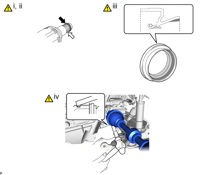
(1) Coat the front drive shaft hole snap ring with MP grease.
(2) Coat the splines of the front drive inboard joint assembly with Toyota genuine CVT fluid FE.
(3) Coat the lip of the front drive shaft oil seal with MP grease and Toyota genuine oil seal side lip grease as shown in the illustration.
(4) Align the inboard joint splines, and using a brass bar and a hammer, install the front drive shaft assembly.
NOTICE:
- Face the end gap of the front drive shaft hole snap ring downward.
- Do not damage the front drive shaft oil seal.
- Do not damage the front axle inboard joint boot.
- Make sure to center the front drive shaft assembly during installation to prevent damage to the front drive shaft hole snap ring.
HINT:
Confirm whether the drive shaft is securely driven in by checking the reaction force and sound.
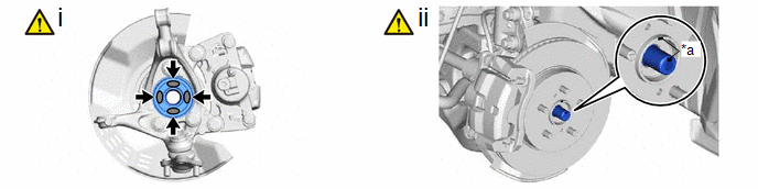
3. CONNECT FRONT DRIVE SHAFT ASSEMBLY
|
*a |
Matchmark |
- |
- |
|
|
Toyota Body Grease W |
- |
- |
(1) Apply 0.1 to 0.3 g (0.00353 to 0.0106 oz.) of Toyota Body Grease W to each of the 4 areas shown in the illustration.
(2) Align the matchmarks and install the front drive shaft assembly to the front axle assembly.
NOTICE:
- Do not push the front axle assembly towards the outside of the vehicle any further than necessary.
- Check that there is no foreign matter on the deflector or contact surfaces.
- Do not damage the front axle outboard joint boot.
- Do not damage the front disc brake dust cover.
- Do not damage the deflector.
4. CONNECT FRONT LOWER NO. 1 SUSPENSION ARM SUB-ASSEMBLY
Click here .gif)
5. INSTALL FRONT STABILIZER LINK ASSEMBLY
|
|
Click here |
6. CONNECT TIE ROD END SUB-ASSEMBLY
|
|
Click here |
7. INSTALL FRONT SPEED SENSOR
|
|
Click here |
8. INSTALL FRONT AXLE SHAFT NUT
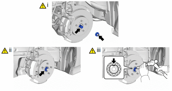
(1) Clean the threaded parts on the front drive shaft assembly and a new front axle shaft nut using non-residue solvent.
NOTICE:
- Be sure to perform this work even when using a new front drive shaft assembly.
- Keep the threaded parts free of oil and foreign matter.
(2) While applying the brakes, using a 30 mm deep socket wrench, install the front axle shaft nut.
Torque:
216 N·m {2203 kgf·cm, 159 ft·lbf}
(3) Using a chisel and a hammer, stake the front axle shaft nut.
9. ADD CONTINUOUSLY VARIABLE TRANSAXLE FLUID
Click here
10. INSPECT FOR CONTINUOUSLY VARIABLE TRANSAXLE FLUID LEAK
Click here
11. INSTALL FRONT WHEELS
Click here
12. INSPECT AND ADJUST FRONT WHEEL ALIGNMENT
Click here
13. INSTALL REAR ENGINE UNDER COVER LH
14. INSTALL REAR ENGINE UNDER COVER RH
15. INSTALL NO. 1 ENGINE UNDER COVER ASSEMBLY
Click here
16. CHECK FOR SPEED SENSOR SIGNAL
Click here
17. PERFORM INITIALIZATION
|
Parking assist monitor system |
|
|
Automatic headlight beam level control system |
|


